Eureka AIR delivers breakthrough ideas for toughest innovation challenges, trusted by R&D personnel around the world.

Method For Using A Geometrical Probe With A Spindle Of A Machine Tool, And Machine Tool Configured To Carry Out Such A Method

a technology of geometrical probe and machine tool, which is applied in the direction of computer control, program control, instruments, etc., can solve the problems of inability to guarantee the most instances, unnecessary costly non-productive downtime, and errors in the referencing of workpieces, so as to achieve accurate and accurate determination of the probe-fetching time and speed processing

Active Publication Date: 2019-02-21
GF MACHINING SOLUTIONS AG
View PDF0 Cites 2 Cited by
  • Summary
  • Abstract
  • Description
  • Claims
  • Application Information

AI Technical Summary

Benefits of technology

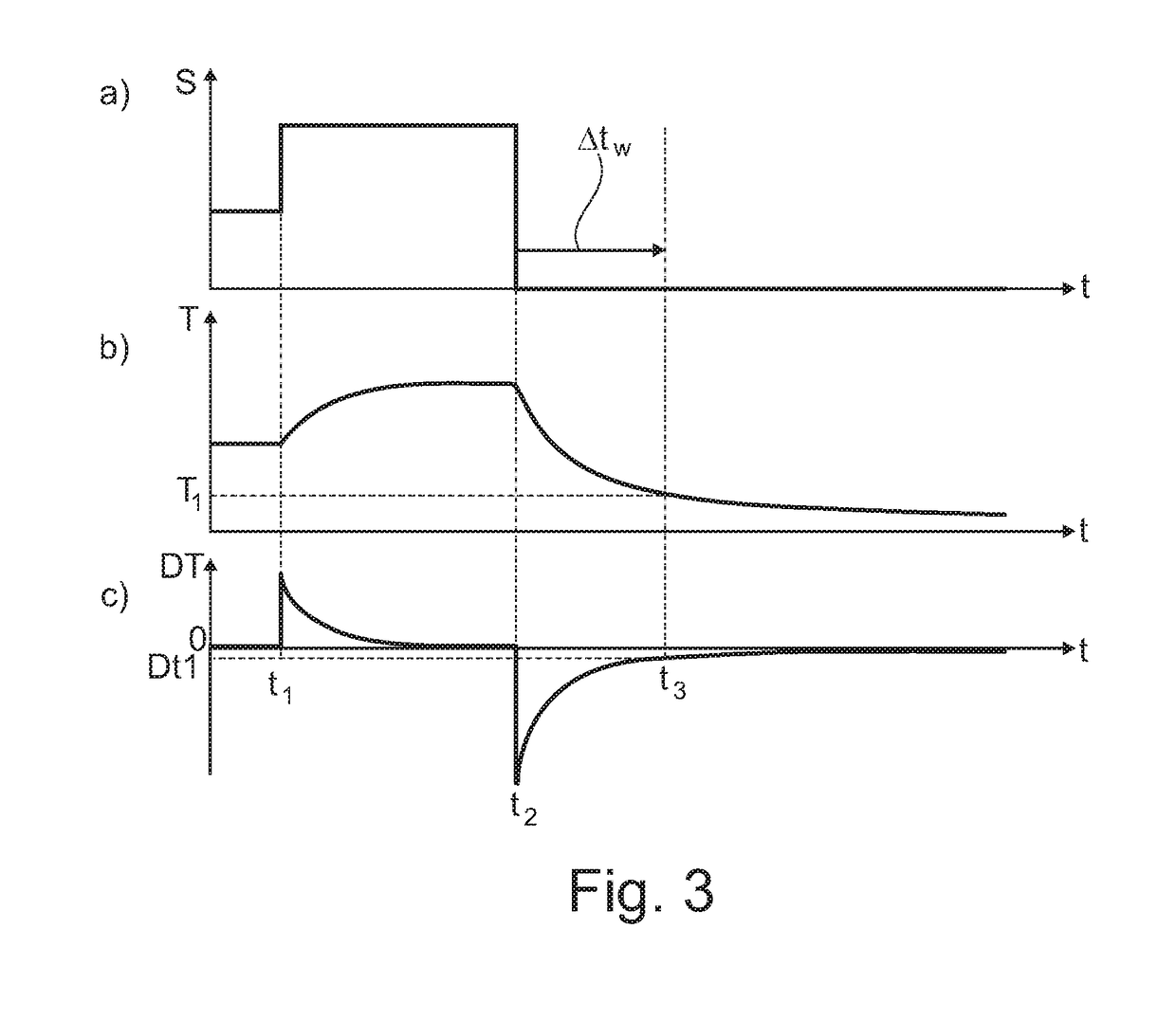
The patent provides a method for using a geometrical probe with a machine tool spindle by measuring the temperature of the spindle and determining the ideal time to fetch the probe based on the temperature measurement. This helps to quickly and accurately determine the thermal state of the spindle, avoiding costly downtime of the machine tool. The method can also be influenced by the user's preferences through a preset machine user parameter. Overall, this method provides precise and efficient information about the thermal state of the spindle and reduces downtime of the machine tool.

Problems solved by technology

This leads to a transient thermal behavior of the spindle-probe assembly modifying the position of the geometrical probe, in particular a probe end tip of the geometrical probe, wherein this modification might induce errors in the referencing of the workpiece.
However, defining such a conservative waiting time which is long enough for all practical purposes might well be too long for most instances, thus leading to unnecessary costly non-productive downtime.
In fact, this cannot be guaranteed for most instances.
Thermal modelling, taking into account a history of the spindle activity and / or the spindle shaft, is cumbersome and leads to imprecise results.

Method used


Image

  • Method For Using A Geometrical Probe With A Spindle Of A Machine Tool, And Machine Tool Configured To Carry Out Such A Method
  • Method For Using A Geometrical Probe With A Spindle Of A Machine Tool, And Machine Tool Configured To Carry Out Such A Method

Examples


Embodiment Construction

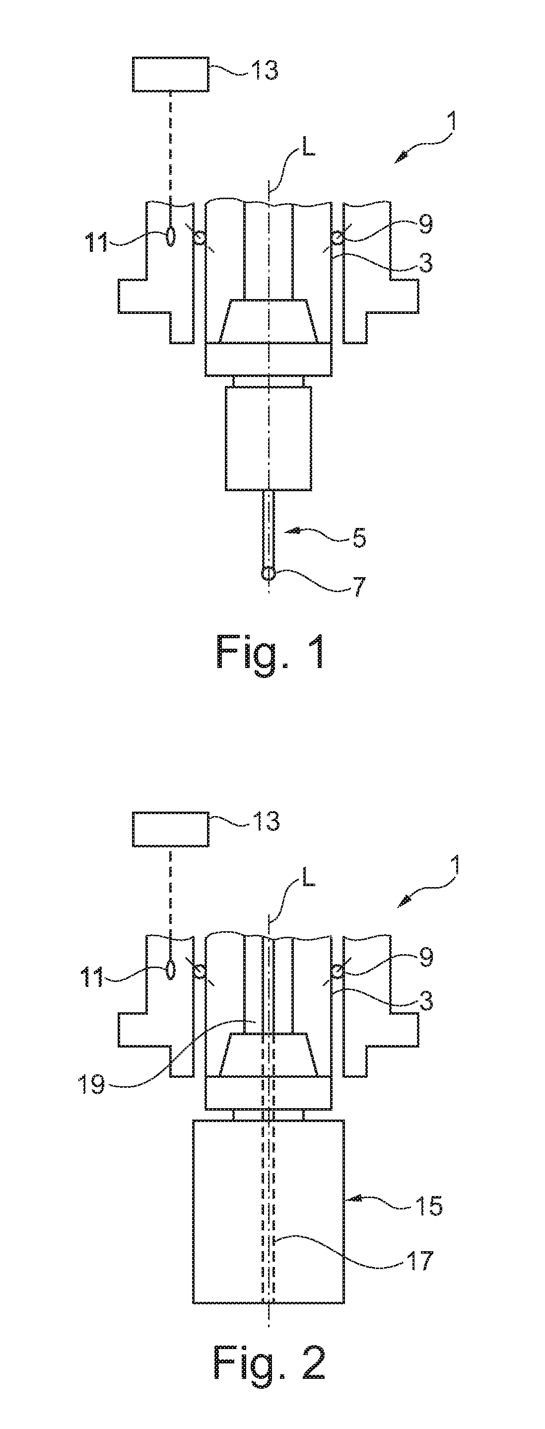
[0039]FIG. 1 shows a schematic representation of an embodiment of a machine tool 1, the machine tool 1 having a spindle 3, and a geometrical probe 5 which is configured to be—preferably automatically—coupled to the spindle 3 for position measurement in particular at a surface of a workpiece to be machined with the machine tool 1. The geometrical probe 5 is preferably configured as a touch probe, as schematically shown in FIG. 1, and thus configured to measure positions at the workpiece by contacting the workpiece surface with a probe end tip 7. Additionally or alternatively, the machine tool 1 is preferably configured as a milling machine.

[0040]Typically, when the geometrical probe 5 is attached to the spindle 3 and used for position measurement at a workpiece, the spindle 3 is in a non-rotating state. The machine tool 1 preferably has a tool magazine comprising at least one machining tool or a plurality of machining tools for machining a workpiece, wherein the at least one machinin...


PUM


Abstract

A method for using a geometrical probe (5) with a spindle (3) of a machine tool (1), wherein a probe fetch waiting state of the machine tool (1), at least one temperature parameter related to a temperature of the spindle (3) of the machine tool (1) is determined by measuring at least one temperature value for the spindle (3), and time for fetching the geometrical probe (5) is determined depending on the at least one temperature parameter.

Description

CROSS REFERENCE TO RELATED APPLICATION[0001]This application claims the benefit and priority of European Patent Application No. 17 186 241.0, filed Aug. 15, 2017. The entire disclosure of the above application is incorporated herein by reference.BACKGROUNDTechnical Field[0002]The invention is related to a method for using a geometrical probe with a spindle of a machine tool, and a machine tool configured to carry out such a method.[0003]On machine tools, in particular, e.g. a milling machine, an exact reference position of a part to be machined is typically measured using a geometrical probe, such as a touch probe. The geometrical probe is mounted into a spindle of the machine tool and used to measure at least one position with respect to the part to be machined while the spindle is in a non-rotating state. The geometrical probe may be exchanged against machining tools such as e.g. a miller, a drill bit, a reamer, or any other appropriate tool configured to machine a workpiece, i.e....

Claims


Application Information

Patent Timeline
IPC IPC(8): G05B19/404G05B19/4065B23Q17/09G01B11/00
CPCB23Q2717/006G05B19/404G05B19/4065B23Q17/0985G05B2219/37043G05B2219/37428G05B2219/37001G05B2219/37008G05B2219/37027G01B11/007B23Q17/00B23Q17/22G05B19/409G05B19/406
Inventor MEIER, JONASBESUCHET, JEAN-PHILIPPESCHNEIDER, KURT
Owner GF MACHINING SOLUTIONS AG
Why Eureka
Eureka Blog
Learn More