Focus stacking for retinal imaging

a retinal imaging and focus stacking technology, applied in the field of imaging technologies, can solve the problems of reducing image quality, affecting image fidelity, etc., and achieving the effect of improving image fidelity

Active Publication Date: 2019-02-28
VERILY LIFE SCI LLC
View PDF1 Cites 3 Cited by
  • Summary
  • Abstract
  • Description
  • Claims
  • Application Information

AI Technical Summary

Problems solved by technology

This scattered light shows up in the retinal image as lens flare, which is deleterious to the image quality.
The brighter the illumination, the more pronounced the lens flare, which undermines the goal of improving image fidelity.

Method used


Image

  • Focus stacking for retinal imaging
  • Focus stacking for retinal imaging
  • Focus stacking for retinal imaging

Examples


Embodiment Construction

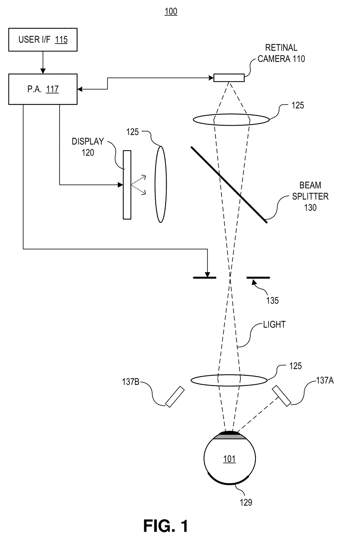
[0012]Embodiments of an apparatus and method for focus stacking for retinal imaging are described herein. In the following description numerous specific details are set forth to provide a thorough understanding of the embodiments. One skilled in the relevant art will recognize, however, that the techniques described herein can be practiced without one or more of the specific details, or with other methods, components, materials, etc. In other instances, well-known structures, materials, or operations are not shown or described in detail to avoid obscuring certain aspects.

[0013]Reference throughout this specification to “one embodiment” or “an embodiment” means that a particular feature, structure, or characteristic described in connection with the embodiment is included in at least one embodiment of the present invention. Thus, the appearances of the phrases “in one embodiment” or “in an embodiment” in various places throughout this specification are not necessarily all referring to...


PUM


Abstract

A method of imaging an interior of an eye includes illuminating the interior of the eye with one or more beams of light from a light source, and said illuminating is configured to trigger a change to a pupil of the eye. An image sensor captures a sequence of images of light reflected by the interior of the eye during an expected timeframe when a width of the pupil is changing in response to said illuminating. A processing apparatus combines images in the sequence of images to form a composite image having a larger depth of field than a depth of field of each of the images in the sequence of images. The depth of field for each of the images corresponds to the width of the pupil when each of the images is captured.

Description

REFERENCE TO RELATED APPLICATION[0001]This application claims the benefit of U.S. application Ser. No. 62 / 551,708, filed on Aug. 29, 2017, the contents of which are incorporated herein by reference.TECHNICAL FIELD[0002]This disclosure relates generally to imaging technologies, and in particular, relates to retinal imaging.BACKGROUND INFORMATION[0003]Retinal imaging is a part of basic eye exams for screening, field diagnosis, and progress monitoring of many retinal diseases. A high fidelity retinal image is important for accurate screening, diagnosis, and monitoring. Bright illumination of the posterior interior surface of the eye (e.g., retina) through the pupil improves image fidelity while often creating optical aberrations or image artifacts, such as lens flare. Lens flare is a phenomenon where light scatters off of interior components of a lens system due to internal reflections, refractive index changes at various internal boundaries, imperfections, or otherwise. This scattered...

Claims


Application Information

Patent Timeline
Patent Type & Authority Applications(United States)
IPC IPC(8): A61B3/00G06T5/00G06T5/50A61B3/10
CPCA61B3/0025G06T5/003G06T5/50A61B3/10G06T2207/10152G06T2207/20216G06T2207/30041A61B3/0008A61B3/112A61B3/12
Inventor LAMBA, DHRUVKAVUSI, SAM
Owner VERILY LIFE SCI LLC
Why Eureka
Try Eureka