Method and apparatus for imaging using polarimetry and matrix based image reconstruction

a matrix based image and matrix technology, applied in the direction of optical radiation measurement, instruments, polarising elements, etc., can solve the problems of pixel to pixel noise, limiting diagnosis and evaluation of structures viewed in confocal, and major limitations to the recognition of features

Inactive Publication Date: 2005-08-09
GARCIA JUAN MANUEL BUENO +1
View PDF1 Cites 21 Cited by
  • Summary
  • Abstract
  • Description
  • Claims
  • Application Information

AI Technical Summary

Benefits of technology

[0042]d) constructing a spatially resolved matrix of the object from the detected light intensity signals and from said spatially resolved matrix constructing spatially resolved images of the object or region of interest of the object for a set

Problems solved by technology

Image quality in any imaging system can often be limited by noise including speckle noise in coherent illumination, or by lower resolution or a lack of contrast due to scattered light or light from secondary light sources.
Major limitations to the recognition of fea

Method used


Image

  • Method and apparatus for imaging using polarimetry and matrix based image reconstruction
  • Method and apparatus for imaging using polarimetry and matrix based image reconstruction
  • Method and apparatus for imaging using polarimetry and matrix based image reconstruction

Examples


Embodiment Construction

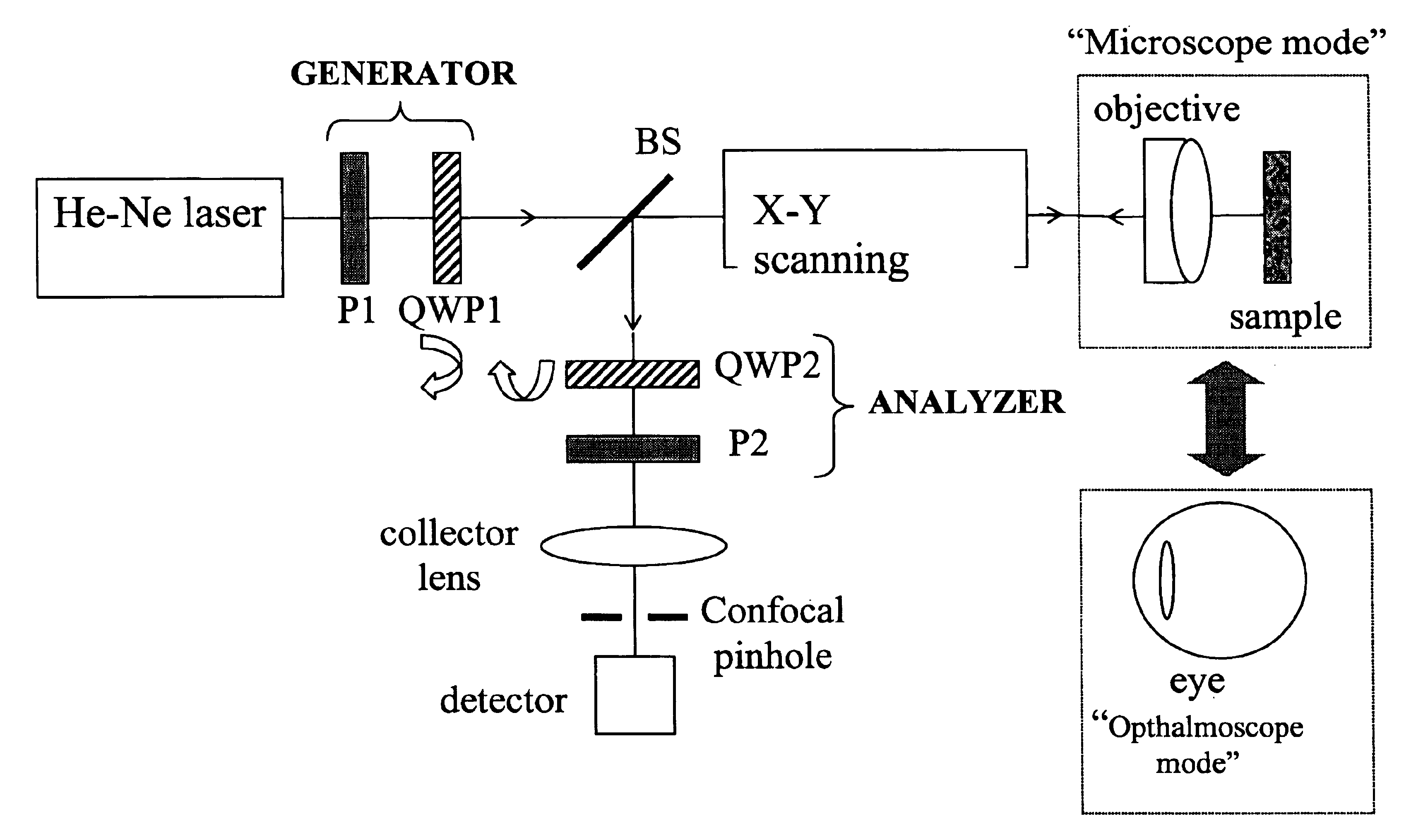
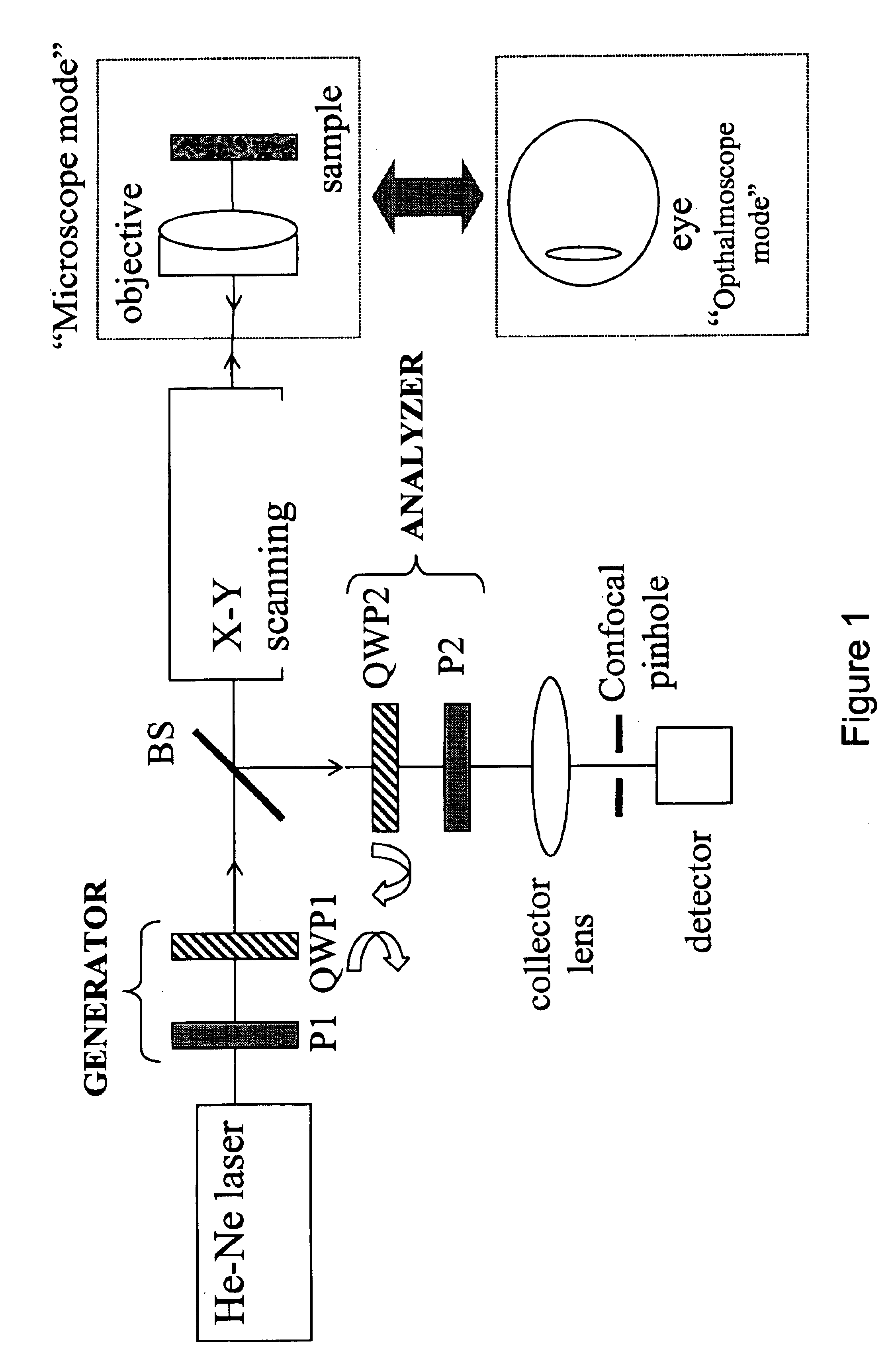
[0083]Broadly, the present invention provides a method of obtaining images of an object where the object is illuminated by incident beam(s) of selectively polarized light or nonpolarized light and the images reflected or transmitted by the object for each different incident beam polarization is analised with respect to its polarization and then recorded using methods which resolve individual image points from the object. Matrix methods are used to reconstruct multiple images from the recorded image signals and the best image selected.

[0084]The method may be implemented using an optical scanning system or a scanning stage on which the object is placed such as for example a scanning laser system. The scans may be 2 dimensional in any combination of 2 perpendicular axes or 3 dimensional. In one embodiment the method and apparatus use Mueller-matrix polarimetry to reduce noise and improve images of light reflected from the sample recorded with the optical scanning system. In a second em...


PUM


Abstract

The present invention provides a method and apparatus for improving the signal to noise ratio, the contrast and the resolution in images recorded using an optical imaging system which produces a spatially resolved image. The method is based on the incorporation of a polarimeter into the setup and polarization calculations to produce better images. After calculating the spatially resolved Mueller matrix of a sample, images for incident light with different states of polarization were reconstructed. In a shorter method, only a polarization generator is used and the first row of the Mueller matrix is calculated. In each method, both the best and the worst images were computed. In both reflection and transmission microscope and Macroscope and ophthalmoscope modes, the best images are better than any of the original images recorded. In contrast, the worst images are poorer. This technique is useful in different fields such as confocal microscopy, Macroscopy and retinal imaging.

Description

CROSS REFERENCE TO RELATED UNITED STATES PATENT APPLICATIONS[0001]This patent application relates to U.S. Provisional patent application Ser. No. 60 / 379,417 filed on May 13, 2002, entitled CONFOCAL SCANNING LASER OPHTHALMOSCOPY IMPROVEMENT BY USING MUELLER-MATRIX POLARIMETRY, and U.S. Provisional patent application Ser. No. 60 / 417,641 filed on Oct. 11, 2002, entitled METHOD AND APPARATUS FOR IMAGING USING POLARIMETRY AND MATRIX BASED IMAGE RECONSTRUCTION.FIELD OF THE INVENTION[0002]This invention relates generally to a method of obtaining images of objects with optical systems using polarimetry and matrix based image reconstruction of the object, and more particularly the invention relates to obtaining images with a scanning laser optical system using Mueller-matrix polarimetry. This invention also relates to a method of obtaining images of the eye using scanning laser ophthalmoscopy, fundus photography or optical coherence tomography in combination with Mueller-matrix polarimetry.B...

Claims


Application Information

Patent Timeline
IPC IPC(8): A61B3/12G02B21/00G02B5/30G02B27/28
CPCG02B5/3025G02B21/0028G02B21/0068G02B21/008G02B27/286A61B3/1025Y10S359/90
Inventor GARCIA, JUAN MANUEL BUENOCAMPBELL, MELANIE C. W.
Owner GARCIA JUAN MANUEL BUENO
Why Eureka
Try Eureka