Lamination molding apparatus and method for producing three-dimensional molded object

a three-dimensional molded object and lamination molding technology, applied in the direction of additive manufacturing, manufacturing tools, manufacturing processes, etc., can solve the problem of tensile stress remaining in the solidified layer, and achieve the effect of reducing the tensile stress of metal and residual stress of the molded produ

Active Publication Date: 2019-02-28
SODICK CO LTD
View PDF2 Cites 6 Cited by
  • Summary
  • Abstract
  • Description
  • Claims
  • Application Information

AI Technical Summary

Benefits of technology

[0009]Accordingly, the martensitic transformation can be intentionally made to take place with the solidified layer, thereby reducing the tensile stress of metal by shrinkage with the compressive stress by the martensitic transformation. Accordingly, the residual stress of the molded product can be controlled.

Problems solved by technology

However, since the solidified layer is adhered to the adjacent solidified layer or the molding plate, the amount of such shrinkage is restricted, and thus a tensile stress remains in the solidified layer.

Method used


Image

  • Lamination molding apparatus and method for producing three-dimensional molded object
  • Lamination molding apparatus and method for producing three-dimensional molded object
  • Lamination molding apparatus and method for producing three-dimensional molded object

Examples


first embodiment

[0040]Hereinafter, the first embodiment of the present invention will be described by referring to the drawings. Here, the characteristic matters shown in the embodiments can be combined with each other.

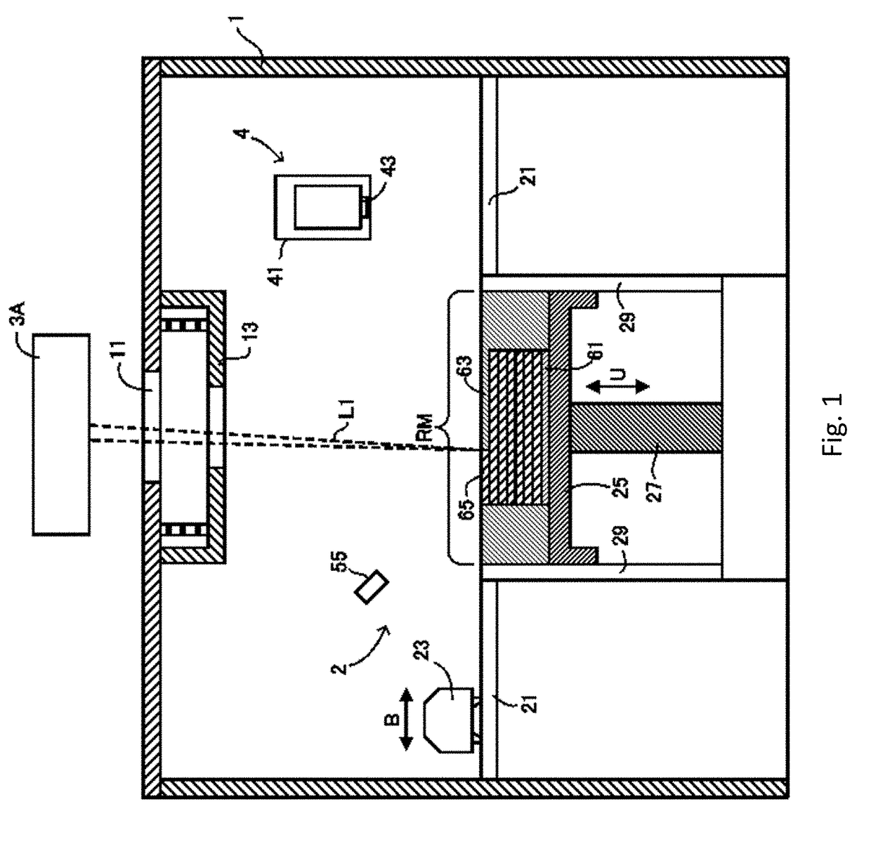
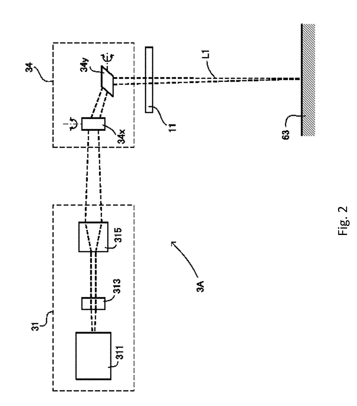
[0041]Regarding the lamination molding apparatus according to the first embodiment of the present invention, a material layer 63 made of material powder is formed, and then a predetermined portion of the material layer 63 is irradiated with a first beam L1 to sinter or melt the material powder at the irradiated position. These processes are repeated to laminate a plurality of solidified layers 65 to mold a three-dimensional molded product. As shown in FIG. 1, the lamination molding apparatus of the present invention comprises a chamber 1, a material layer former 2, an irradiation unit 3A, and a cutting device 4.

[0042]A clean inert gas is supplied into the chamber 1 covering the predetermined molding region RM, and an inert gas containing fume generated during sintering or melting the...


PUM

PropertyMeasurementUnit
heightaaaaaaaaaa
temperatureaaaaaaaaaa
start temperatureaaaaaaaaaa

Abstract

A lamination molding apparatus, includes a material layer former to form a material layer; a first emitter to form a solidified layer by irradiating the material layer with a first beam; and a thermal adjuster to adjust a temperature of at least a portion of the solidified layer to at least one of a predetermined first temperature and a predetermined second temperature. The temperature of at least the portion of the solidified layer is adjusted to the first temperature, and then to the second temperature. When the first temperature is referred to as T1, the second temperature is referred to as T2, a martensite start temperature of the solidified layer is referred to as Ms, and a martensite finish temperature of the solidified layer is referred to as Mf, all of the following relations of T1≥Mf, T1>T2, and T2≤Ms are satisfied.

Description

[0001]Priority is claimed on Japanese application No. 2017-165090, filed Aug. 30, 2017, on Japanese application No. 2018-033842, filed Feb. 27, 2018, and on Japanese application No. 2018-104432, filed May 31, 2018, the content of which are incorporated herein by reference.FIELD[0002]The present invention relates to a lamination molding apparatus and to a method for manufacturing lamination molded product.BACKGROUND[0003]There are several methods for conducting lamination molding of metal. Known methods are Selective Laser Sintering (SLS), Selective Laser Melting (SLM), Electron Beam Sintering (EBS), Electron Beam Melting (EBM), Laminated Object Manufacturing (LOM), and the like. According to such methods, a material layer made of a metal material is formed, and then a predetermined portion of the material layer is irradiated with a beam such as laser beam or electron beam to sinter or melt the material layer at the irradiated position. These processes are repeated to laminate a plur...

Claims


Application Information

Patent Timeline
Patent Type & Authority Applications(United States)
IPC IPC(8): B22F3/105B22F3/10
CPCB22F3/1055B22F3/1007B22F3/1028B22F2201/11B22F2203/11B22F2203/03B22F2003/1058B22F2003/1057B33Y10/00B33Y30/00B33Y40/00B22F3/24B22F2003/247B22F10/00B22F12/22B22F12/20B22F12/49B22F12/10B22F10/362B22F12/90B22F12/67B22F12/41B22F2998/10B22F2999/00B22F10/28B33Y40/10B22F2003/248B29C2035/0838B29C2035/0877B29C64/153B29C64/295C21D1/06C21D2211/001C21D2211/008C21D2221/00Y02P10/25B33Y40/20B22F10/10B22F10/20B22F10/30B22F12/00B33Y70/10B23K15/0086
Inventor ARAIE, ICHIRONAMBU, KAZUFUMIHIROTA, ATSUSHIAMIOKA, HIROSHIOKAZAKI, SHUJI
Owner SODICK CO LTD
Why Eureka
Try Eureka