Gas Turbine

a technology of gas turbine and side seal plate, which is applied in the direction of gas turbine plants, machines/engines, leakage prevention, etc., can solve the problems of requiring two mutually incompatible characteristics of rigidity and flexibility, and generating vibrations, so as to prevent leakage of combustion air, the sealing performance of the side seal plate deteriorates, and the sealing performance of the floating seal plate also deteriorates

Inactive Publication Date: 2019-02-28
MITSUBISHI HITACHIPOWER SYST LTD
View PDF0 Cites 2 Cited by
  • Summary
  • Abstract
  • Description
  • Claims
  • Application Information

AI Technical Summary

Benefits of technology

[0012]Usually, the side seal plate is displaced in accordance with relative displacement of two combustors as objects to be sealed due to thermal deformation. For example, in the case where the relative position of the adjacent combustors is greatly changed in the axial direction, the sealing grooves of the frames of the transition pieces are mutually deviated in the axial direction, and a gap is likely to be caused between the side seal plate and the sealing groove. To cope with this, there is provided so-called “play” for adjusting the gap between the side seal plate and the sealing groove and for allowing a positional change of the side seal plate. Due to the difference in pressure between the combustion air and the combustion gas acting on each surface of the flat side seal plate, the side seal plate moves and is pressed against the opposite sealing groove, whereby the sealing performance of the side seal plate is maintained.
[0013]However, in the case where the side seal plates and the floating seal plates are connected together with a view to preventing leakage of combustion air from the gap between the frame corner portions of the adjacent transition pieces, the side seal plate is constrained by the floating seal plates and cannot be displaced, resulting in generation of a space between the side seal plate and the opposite sealing groove. As a result, the sealing performance of the side seal plate deteriorates. In this case, a force is also applied to the floating seal plates constraining the displacement of the side seal plate, and, in some cases, a space is also generated between the floating seal plate and the opposite sealing groove. As a result, the sealing performance of the floating seal plate also deteriorates.

Problems solved by technology

Further, in the gas turbine, there is likely to be generated a vibration accompanying the rotation of the gas turbine and the circulation of the working fluid.
That is, two mutually incompatible characteristics of rigidity and flexibility are required of the sealing plates of this sealing structure.

Method used


Image

  • Gas Turbine
  • Gas Turbine
  • Gas Turbine

Examples


first embodiment

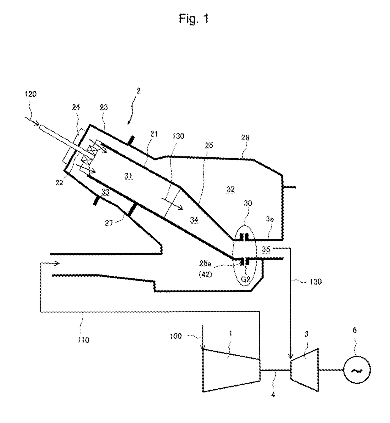
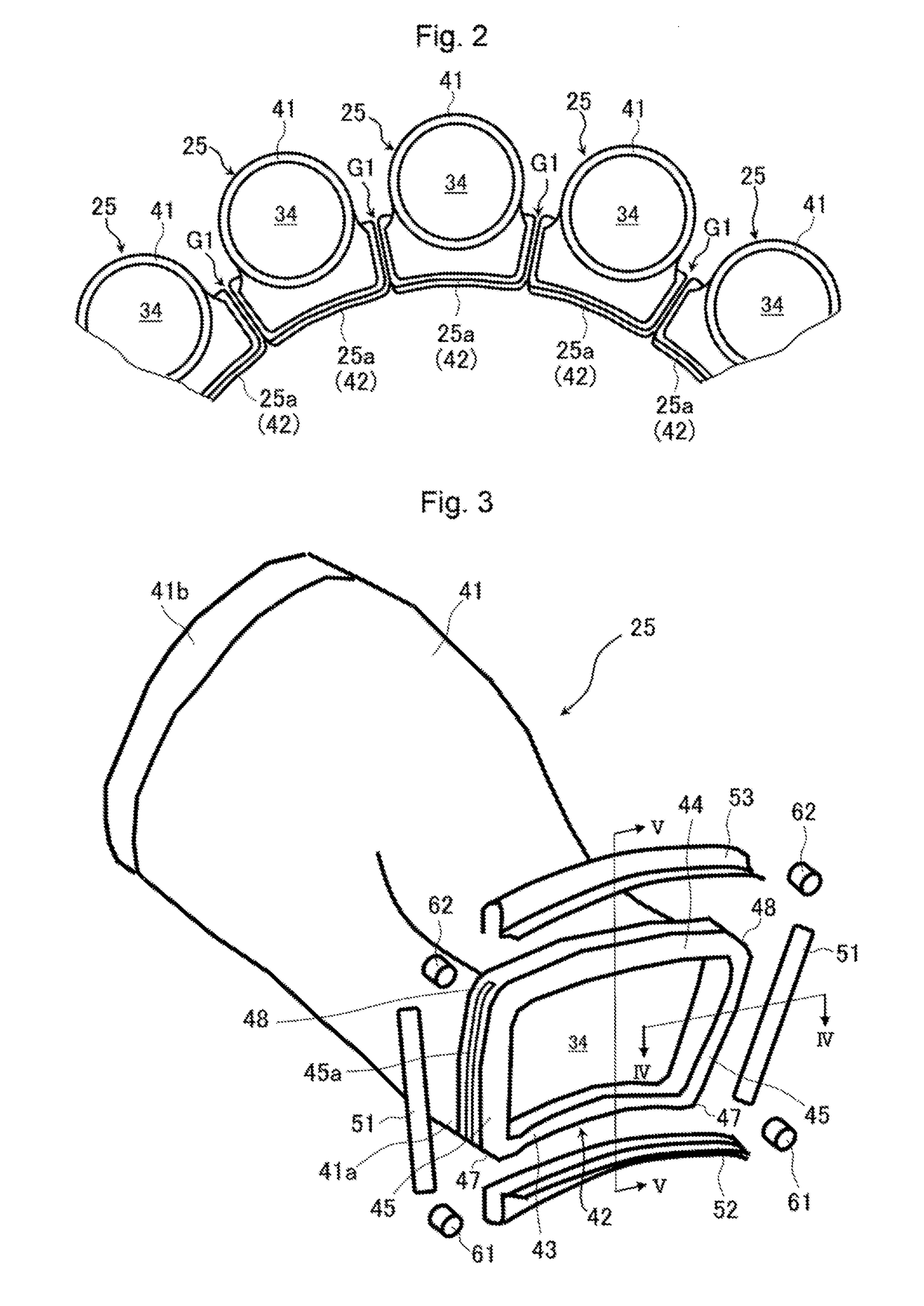
[0034]First, a structure of a gas turbine of a first embodiment of the present invention will be described with reference to FIGS. 1 and 2. FIG. 1 is a schematic diagram illustrating the gas turbine according to the first embodiment of the present invention. FIG. 2 is a diagram illustrating an arrangement of transition pieces of combustors constituting the gas turbine according to the first embodiment of the present invention as seen from the upstream side in the combustion gas flowing direction. In FIG. 1, the left-hand side of the combustor illustrated is the upstream side of the combustion gas, and the right-hand side thereof is the downstream side of the same.

[0035]In FIG. 1, the gas turbine includes a compressor 1 which takes in ambient air 100 and compresses it to generate high pressure combustion air 110, a plurality of combustors 2 (of which only one is shown in FIG. 1) which combust a mixture of the combustion air (compressed air) 110 introduced from the compressor and a fu...


PUM


Abstract

A gas turbine has a sealing structure at a connection portion between the transition pieces and a turbine inlet portion. A frame of the transition piece has an inner frame portion extending in the circumferential direction, an outer frame portion situated radially outside the inner frame portion, and a pair of side frame portions provided between both side end portions of the inner frame portion and the outer frame portion. The sealing structure includes an inner circumferential seal member and an outer circumferential seal member for sealing a gap between the inner frame portion and the outer frame portion and the turbine inlet portion, a side seal member for sealing a gap between the adjacent side frame portions, a first obstacle arranged in a gap between first corner portions adjacent to each other, and a second obstacle arranged in a gap between second corner portions adjacent to each other. The first obstacle and the second obstacle are in contact with the side seal member at the side of the turbine inlet portion.

Description

BACKGROUND OF THE INVENTION1. Field of the Invention[0001]The present invention relates to a gas turbine and, more specifically, to a gas turbine which has a sealing structure at a connection portion between the outlet side end portions of tail portions of a plurality of combustors arranged in an annular fashion and the inlet portion of the turbine.2. Description of the Related Art[0002]Among various types of gas turbines, there exists a so-called multi-can type gas turbine equipped with a plurality of gas turbine combustors (hereinafter referred to as the combustors) each of which individually has a combustion chamber where combustion gas is generated. In the multi-can type gas turbine, there are usually arranged in an annular fashion a plurality of combustors on the outer side of the rotation shaft of the gas turbine. Each combustor includes a cylindrical combustion liner having a combustion chamber therein and a transition piece for guiding a high temperature and high pressure co...

Claims


Application Information

Patent Timeline
Patent Type & Authority Applications(United States)
IPC IPC(8): F01D9/02F01D11/00F02C7/28
CPCF01D9/023F01D11/005F02C7/28F05D2240/57
Inventor OKAZAKI, HIROFUMIMIURA, KEISUKE
Owner MITSUBISHI HITACHIPOWER SYST LTD
Why Eureka
Try Eureka