Eureka AIR delivers breakthrough ideas for toughest innovation challenges, trusted by R&D personnel around the world.

Integrated Heat And Energy Recovery Ventilator System

a ventilator system and integrated technology, applied in ventilation systems, lighting and heating apparatus, heating types, etc., can solve the problems of unbalanced air flow, unbalanced, and inconvenient installation of air exchange devices, so as to improve the efficiency of ventilation and heating, and reduce the effect of odor

Active Publication Date: 2019-02-28
STEVEN WINTER ASSOCS
View PDF8 Cites 12 Cited by
  • Summary
  • Abstract
  • Description
  • Claims
  • Application Information

AI Technical Summary

Benefits of technology

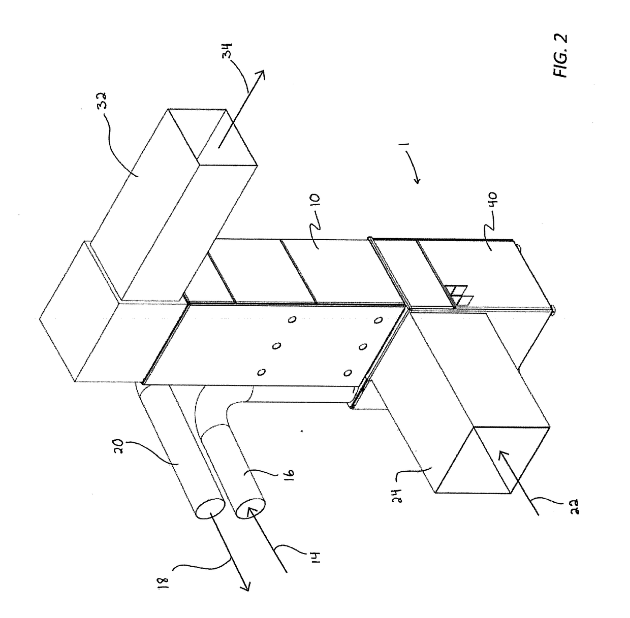
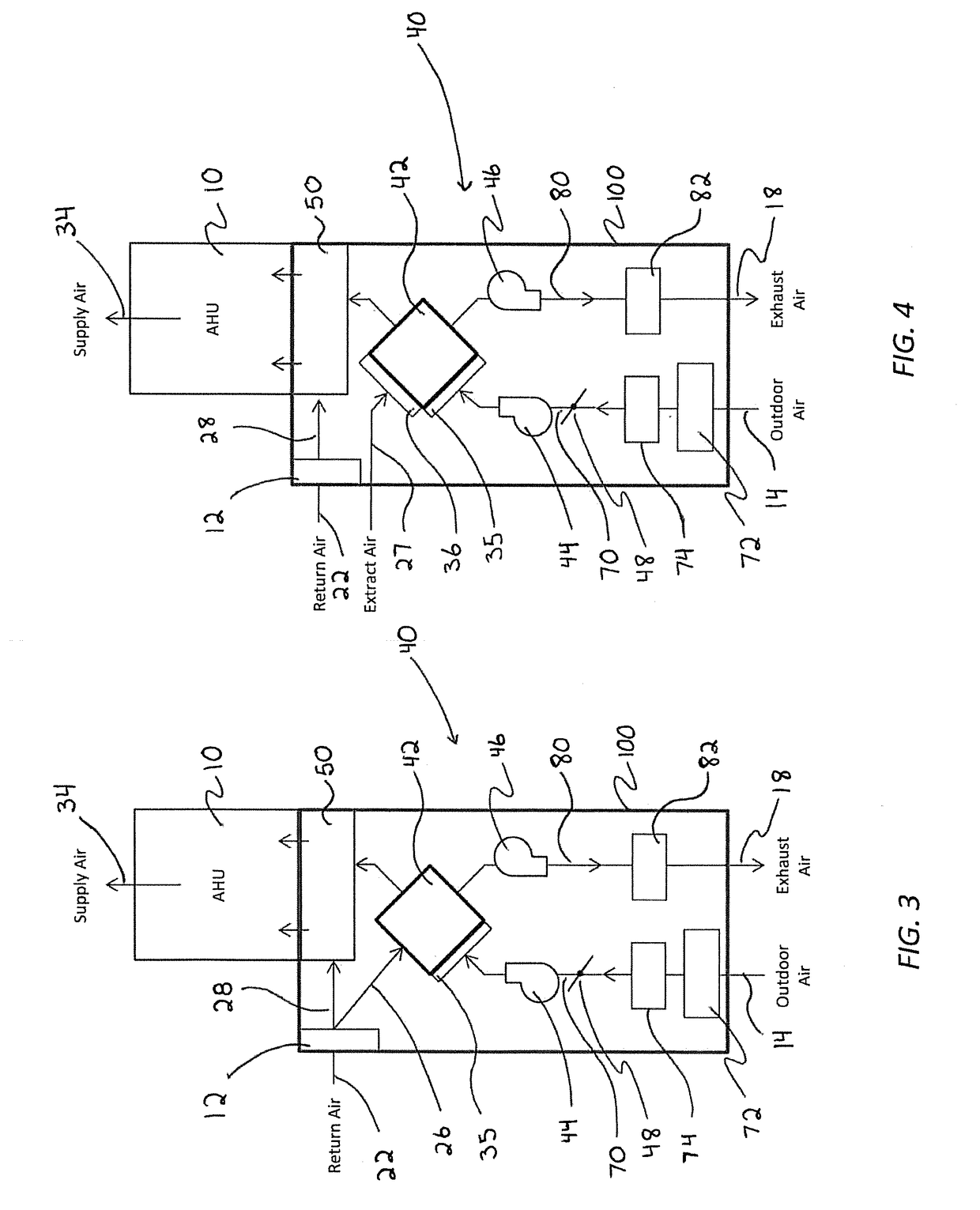
The present invention is a heat recovery ventilator (HRV) and / or energy recovery ventilator (ERV) that can be integrated into a residential capacity air handling unit (AHU). It uses an outdoor air heat exchanger (AAE) and a variable-speed fan to adjust the outdoor air flow rate based on the needs of the space. The tempered outdoor air is mixed with return air before being delivered to the space and exhausts the air to outdoors through a separate pathway. A control system ensures the desired ventilation flow rates are maintained. The invention has a small footprint, requires less air duct installation and connections, and provides continuous control and verification of the desired ventilation rates.

Problems solved by technology

As energy efficiency standards and construction techniques have improved, new and retrofitted buildings have become more air-tight; the reduced outside air infiltration in such buildings can result in poor indoor air quality.
Installation of an air exchange device requires additional space and costs beyond a conventional heating and / or cooling system.
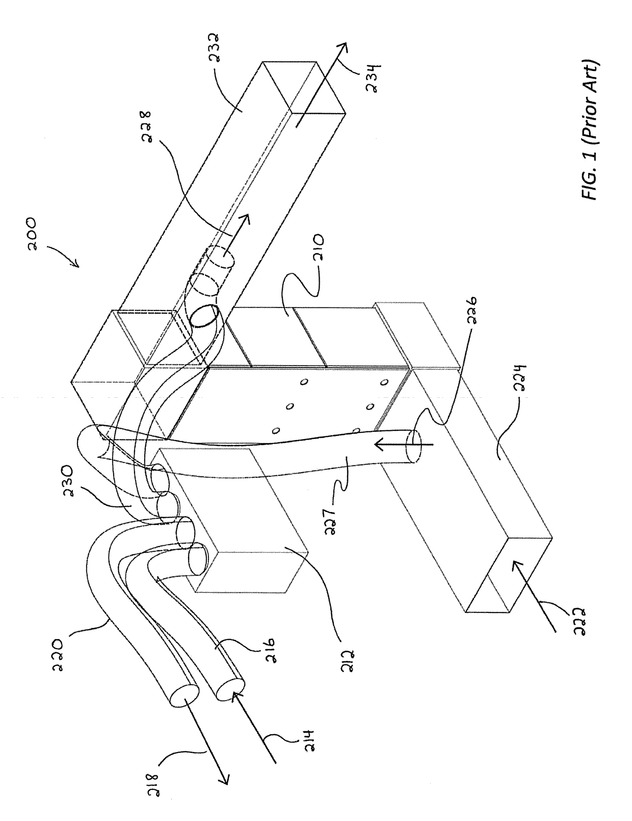
HRV and ERV products that are attached to heating and / or cooling distribution systems, rather than using a dedicated distribution system, often have short-circuiting problems (where fresh outdoor air can be exhausted before it is distributed to occupied space) and unbalanced air flow problems.
In addition, these units are often incorrectly ducted, have improper clearances for maintenance, and have high electric power consumption.
In current standard practice, controls for ventilation are typically poorly integrated (if at all) with controls for heating / cooling.
Desired ventilation flow rates are often not achieved due to system pressure fluctuations and negative pressures caused by operation of the heating / cooling air handler unit and poor ducting design.
Both outdoor air and exhaust air flow rates can vary significantly, resulting in the system being unbalanced.
This occurs because the HRV / ERV fan is competing against large static pressures and duct restrictions associated with improper or suboptimal installation.
A further problem can occur if the supply air 234 pressure causes a reverse flow of the tempered intake air 228.
While this may alleviate some concerns with supply side pressures, it is not straightforward to implement and is not commonly installed.
Unbalanced air flow can be worsened if the AHU is a variable-speed air handler.
Air flow balancing of typical HRV / ERV equipment is implemented for a particular air flow, e.g. at one specific fan speed setting; so when the AHU operates at other fan speeds, the various air flow rates through the HRV / ERV are likely to be unbalanced.
It is a significant problem that current state of the art HRV / ERV systems applied to ducted heating / cooling systems provide very inconsistent ventilation flow rates.
The ventilation system cannot adapt to intermittent operation and variability of the heating and cooling system.

Method used


Image

  • Integrated Heat And Energy Recovery Ventilator System
  • Integrated Heat And Energy Recovery Ventilator System
  • Integrated Heat And Energy Recovery Ventilator System

Examples


Embodiment Construction

[0034]“Air handling unit” or “AHU” refers to a device containing a blower and heating and / or cooling elements used to regulate and distribute conditioned air as part of a heating, ventilating, and air-conditioning (HVAC) system.

[0035]“Air-to-air exchanger” or “AAE” refers to any exchanger that transfers sensible heat (temperature) or enthalpy (temperature and moisture) between inflow and outflow air streams. Examples of an AAE include a plate heat exchanger, membrane energy exchanger, enthalpy wheel, or heat pipe system.

[0036]“Heat recovery ventilator” or “HRV” refers to a unit containing an AAE that transfers sensible heat (temperature) between inflow and outflow air streams and which is optionally provided with an associated fan(s) or blower(s), damper(s) and a control system.

[0037]“Energy recovery ventilator” or “ERV” refers to a unit containing an AAE that transfers enthalpy (temperature and moisture) between inflow and outflow air streams and which is optionally provided with a...


PUM


Abstract

A heat recovery ventilator (HRV) and / or energy recovery ventilator (ERV) that integrates with a residential capacity air handling unit (AHU) is embodied in a small footprint HRV or ERV unit that connects directly to the return side of an AHU and to outdoor air inlet and exhaust ducts. The ventilator includes a control system incorporating a processor and sensors that control the operation of the system to provide desired ventilation flow rates under varying conditions.

Description

[0001]This invention was made with Government support under cooperative agreement award No. DE-EE0007572 by the Department of Energy. The Government has certain rights in this invention.FIELD OF THE INVENTION[0002]The invention relates to the field of residential HVAC systems, more particularly, to the field of air to air heat / energy exchangers, otherwise known as Heat Recovery Ventilation or Energy Recovery Ventilation (HRV or ERV) Systems.BACKGROUND OF THE INVENTION[0003]As energy efficiency standards and construction techniques have improved, new and retrofitted buildings have become more air-tight; the reduced outside air infiltration in such buildings can result in poor indoor air quality. Accordingly, mechanical ventilation devices have become a frequent element of HVAC systems in homes. Mechanical ventilation devices provide an intake of fresh outside air to a conditioned interior space, and / or exhaust indoor air to the outside. Mechanical ventilation is typically provided by...

Claims


Application Information

Patent Timeline
IPC IPC(8): F24F12/00F24F11/00F24F11/74
CPCF24F12/006F24F11/0001F24F11/74F24F2011/0002F24F2140/30F24F2140/40F24F2012/007Y02B30/70
Inventor PUTTAGUNTA, SRIKANTHALDRICH, ROBBCLEARY, BARNETT
Owner STEVEN WINTER ASSOCS
Why Eureka
Eureka Blog
Learn More