Eureka AIR delivers breakthrough ideas for toughest innovation challenges, trusted by R&D personnel around the world.

Microphone Assembly

Active Publication Date: 2019-02-28
HOSIDEN CORP
View PDF8 Cites 0 Cited by
  • Summary
  • Abstract
  • Description
  • Claims
  • Application Information

AI Technical Summary

Benefits of technology

The invention is a microphone assembly that includes a main board and a microphone. The microphone has a capacitor or a MEMS chip and a case for protection. The microphone board is larger than the case and includes a fixing portion and a connecting portion. The connecting portion is a portion of the microphone board that is electrically and mechanically connected to the main board. This direct electrical and mechanical connection makes it easy to change the orientation and position of the microphone relative to the main board. The connection between the microphone board and the main board is strengthened by the use of multiple electrodes and a holder on the main board. The microphone board also includes a ground conductor and a conductive adhesive portion to reduce the possibility of induced noise. Overall, this microphone assembly has a simplified structure and improved connection strength.

Problems solved by technology

In other words, it is not possible to change the orientation and position of the microphone with respect to the holding case and the circuit board.

Method used


Image

  • Microphone Assembly
  • Microphone Assembly
  • Microphone Assembly

Examples


first embodiment

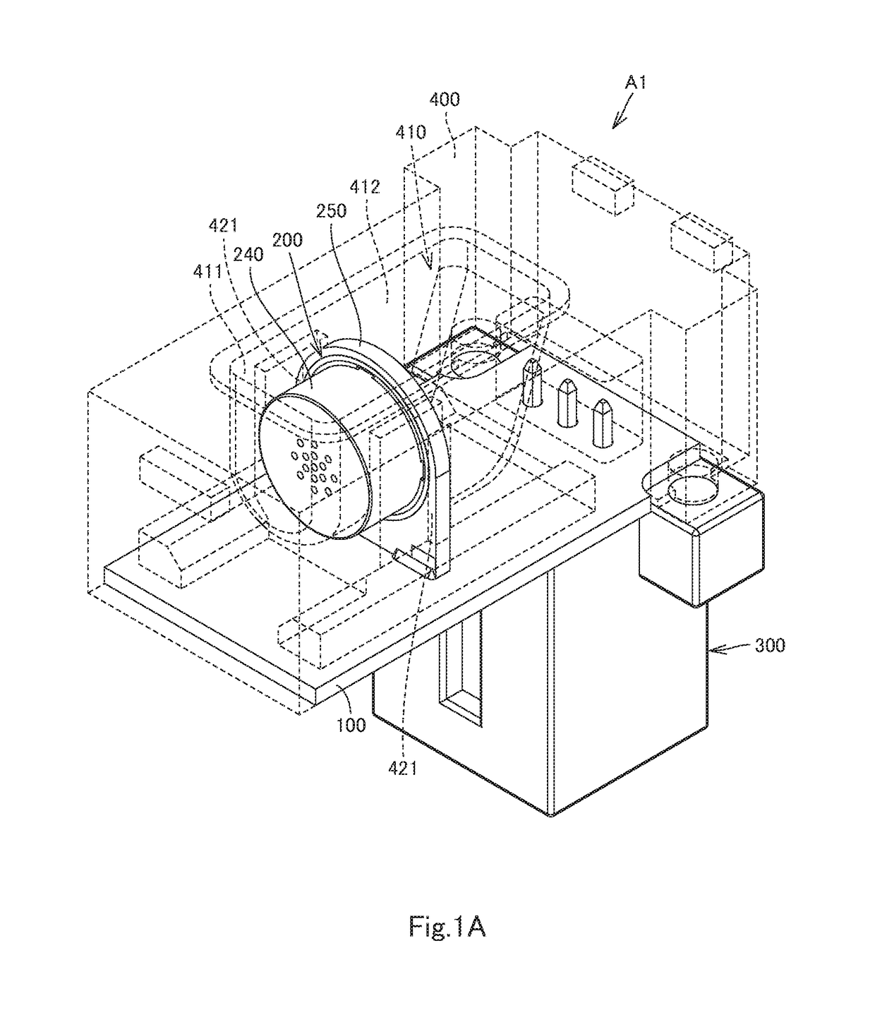
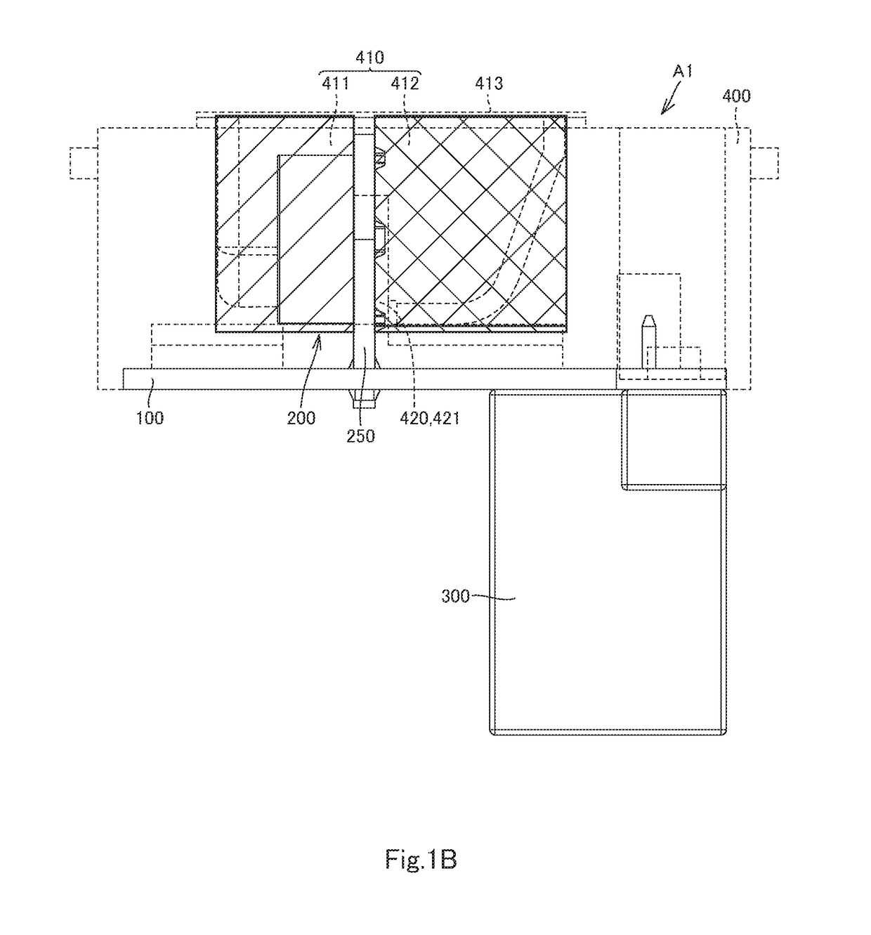
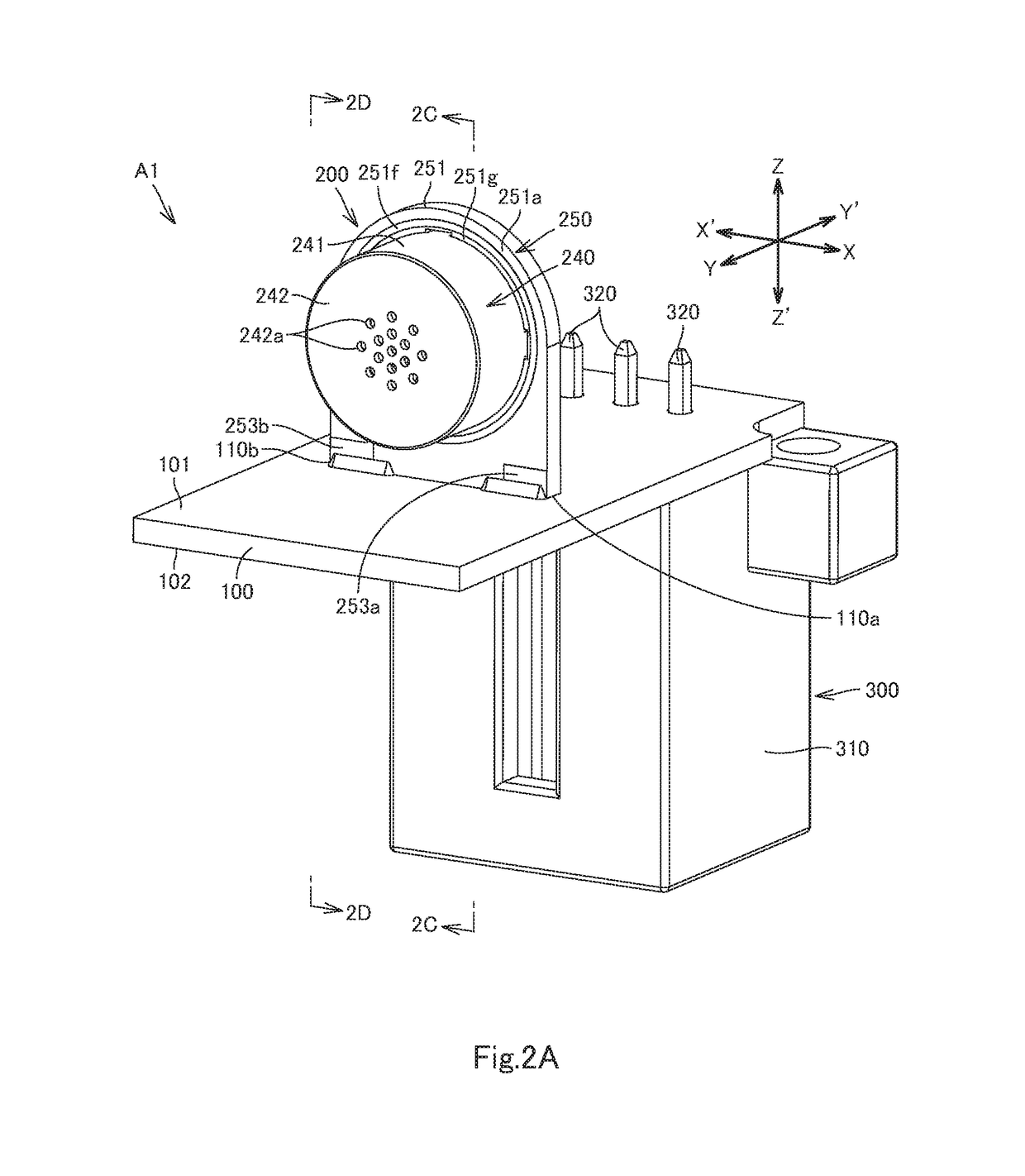
[0033]We now describe a microphone assembly A1 (hereinafter also referred to simply as an assembly A1) according to various embodiments including a first embodiment of the invention, with reference to FIGS. 1A to 3E. FIGS. 1A to 3E shows an assembly A1 of the first embodiment. The Z-Z′ direction, indicated in FIGS. 1A to 2D, is the thickness direction of a main board 100 of the assembly A1 and includes a Z direction and a Z′ direction. The Y-Y′ direction, indicated in FIGS. 1A to 2D, is orthogonal to the Z-Z′ direction. The X-X′ direction, indicated in FIGS. 1A and 2A to 2B, is orthogonal to the Z-Z′ and Y-Y′ directions.

[0034]The assembly A1 includes the main board 100. The main board 100 is a circuit board including a first face 101 on the Z-direction side and a second face 102 on the Z′-direction side.

[0035]The assembly A1 further includes a microphone 200. The microphone 200 includes a diaphragm 211, a fixed electrode 212, a ring 220, a spacer 230, a case 240 having electrical co...

second embodiment

[0087]We now describe a microphone assembly A2 (hereinafter also referred to as an assembly A2) according to various embodiments including a second embodiment of the invention with reference to FIG. 4. FIG. 4 only shows the microphone 200′ of the assembly A2 of the second embodiment. Other components of the are assembly A2 will be described referring to FIGS. 1A to 3E. The assembly A2 has the same configuration as the assembly A1, except that the assembly A2 includes a microphone 200′ of a different configuration from that of the microphone 200 of the assembly A1. The assembly A2 will now be described focusing on the differences from the assembly A1 and omitting overlapping descriptions.

[0088]The microphone 200′ is a MEMS microphone. The microphone 200′ includes a MEMS chip 280 fabricated using microelectromechanical systems (MEMS) technology, a case 240′, and a microphone board 250′. The microphone board 250′ has the same configuration as that of the microphone board 250 of the ass...


PUM


Abstract

A microphone assembly including a main board and a microphone. The microphone includes a capacitor or a MEMS chip, a case accommodating the capacitor or the MEMS chip, and a microphone board electrically connected to the capacitor or the MEMS chip. The microphone board has a larger outer dimension than the case and includes a fixing portion and a connecting portion. The case is fixed onto the fixing portion. The connecting portion is a portion of the microphone board, the portion being located outside the case and electrically and mechanically connected to the main board.

Description

CROSS-REFERENCE TO RELATED APPLICATION[0001]The present application claims priority under 35 U.S.C. § 119 of Japanese Patent Application No. 2017-162257 filed on Aug. 25, 2017, the disclosure of which is expressly incorporated by reference herein in its entirety.BACKGROUND OF THE INVENTIONTechnical Field[0002]The invention relates to microphone assemblies.Background Art[0003]Japanese Patent Application Laid-Open No. 2010-62800 discloses a conventional microphone assembly. The assembly includes a microphone, a soundproof member, a connection cable, a circuit board, a holding case, and a terminal. The microphone is held inside the soundproof member. The holding case is provided with a fitting recess. The fitting recess of the holding case fittingly receives the circuit board and the soundproof member in in this order. The circuit board and the microphone are interconnected via the connection cable inside the fitting recess. In a portion of the holding case above the fitting recess, th...

Claims


Application Information

Patent Timeline
IPC IPC(8): H04R19/04H04R19/00H04R1/04H01R12/52
CPCH04R19/04H04R19/005H04R1/04H01R12/523H04R2201/003H04R1/02H04R1/08H04R1/06H05K3/366H05K2201/10083
Inventor FUKADA, NAOSUKEKANEKO, MAYUMIAWAMURA, RYUJIMOTONAGA, HIDENORINAKANISHI, KENSUKE
Owner HOSIDEN CORP
Why Eureka
Eureka Blog
Learn More