Optimal source electric vehicle heat pump with extreme temperature heating capability and efficient thermal preconditioning

a heat pump and extreme temperature technology, applied in vehicle heating/cooling devices, battery/fuel cell control arrangements, transportation and packaging, etc., can solve the problems of limited capabilities of thermal management systems used in many electric and hybrid vehicles, inherently inefficient approaches, and still relatively complex, etc., to achieve more efficient heating of the cabin, enhance operations, and reduce costs

Active Publication Date: 2019-03-07
TESLA INC
View PDF2 Cites 72 Cited by
  • Summary
  • Abstract
  • Description
  • Claims
  • Application Information

AI Technical Summary

Benefits of technology

[0009]The first embodiment of the present disclosure provides important benefits as compared to the prior systems. By having a compressor and/or cabin blower that may operate in a lossy mode, heat is generated for the cabin by the compressor and/or cabin blower without the need of inefficient high-voltage cabin heaters, which reduces cost. Further, the compressor and/or the cabin blower may be operated across a range of efficient and inefficient operations based upon ambient temperature, battery system temperature, drive train component temperatures, and cabin temperature. As compared to prior heat pump systems, which were ineffective in very low ambient temperatures, the first embodiment supports more efficient heating of the cabin in very low ambient temperatures.
[0010]The first embodiment (and subsequently described embodiments) include aspects, whic

Problems solved by technology

The use of such vehicles, more specifically the use of vehicles which rely on fossil fuels, i.e., gasoline, creates two problems.
First, due to the finite size and limited regional availability of such fuels, major price fluctuations and a generally upward pricing trend in the cost of gasoline are common, both of which can have a dramatic impact at the consumer level.
One of the principal issues involved in designing an efficient electric drive train as well as a vehicle that is “user friendly” is thermal management, primarily due to the required configured conditions of the battery system cells and the need to provide on-demand heating and cooling within the passenger cabin.
As a result, the thermal management systems used in many electric and hybrid vehicles have limited capabilities and/or are overly complex.
Such an approach was inherently inefficient as each subsystem required

Method used


Image

  • Optimal source electric vehicle heat pump with extreme temperature heating capability and efficient thermal preconditioning
  • Optimal source electric vehicle heat pump with extreme temperature heating capability and efficient thermal preconditioning
  • Optimal source electric vehicle heat pump with extreme temperature heating capability and efficient thermal preconditioning

Examples


Embodiment Construction

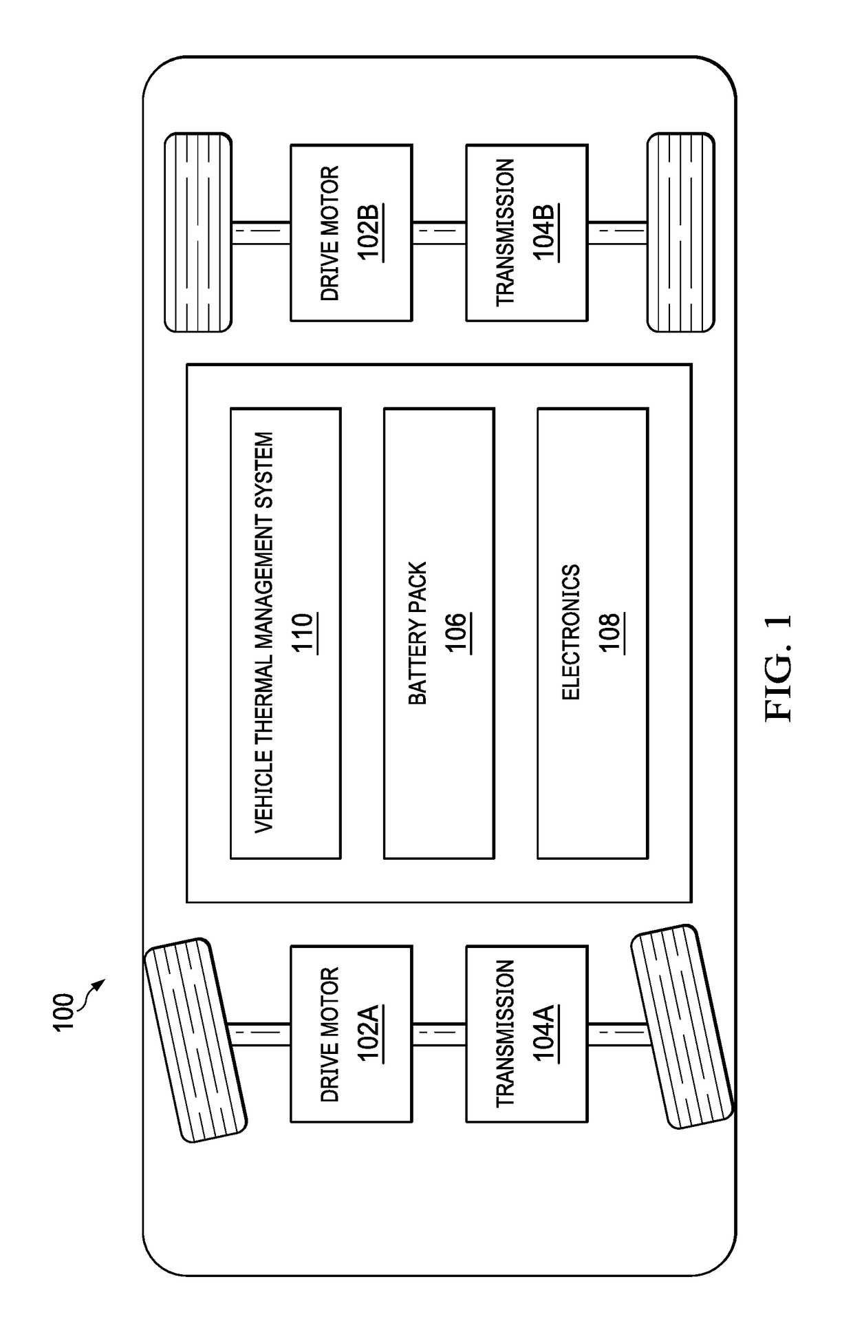
[0059]FIG. 1 illustrates the basic components of a battery powered electric vehicle (electric vehicle) 100. The electric vehicle 100 includes at least one drive motor (traction motor) 102A and / or 102B, at least one transmission 104A and / or 104B coupled to a corresponding drive motor 102A and / or 102B, a battery system 106 and electronics 108 (including drive motor electronics). Generally, the battery system 106 provides electricity to the electronics 108 of the electric vehicle 100 and to propel the electric vehicle 100 using the drive motor 102A and / or 102B. The battery system 106 includes an array of individual batteries constructed according to one or more embodiments of the present invention. The battery system 106, in some embodiments, includes thousands of individual batteries.

[0060]The electric vehicle 100 further includes a vehicle thermal management system 110, which is described herein with reference to a number of embodiments. This vehicle thermal management system 110 inc...


PUM


Abstract

A vehicle thermal management system includes a vehicle heat pump system, a battery system coolant loop, a drive train coolant loop, and control electronics. The vehicle heat pump system includes a compressor, a cabin condenser, a cabin evaporator, a cabin blower, and a chiller. The battery system coolant loop is in thermal communication with a battery system and with the chiller and selectively in thermal communication with the drive train coolant loop. The control electronics control the components of the vehicle thermal management system to heat the cabin, cool the cabin, heat the battery system, cool the battery system, and cool the drive train. The control electronics may control the compressor to operate in an efficient mode or a lossy mode in which the compressor generates heat. The control electronics may also control the components of the vehicle thermal management system to precondition the battery.

Description

CROSS-REFERENCES TO RELATED APPLICATIONS[0001]The present U.S. Utility patent application claims priority pursuant to 35 U.S.C. § 119(e) to U.S. Provisional Application No. 62 / 555,325, entitled “VEHICLE CABIN HEAT PUMP SYSTEM”, filed Sep. 7, 2017, and to U.S. Provisional Application No. 62 / 639,915, entitled “VEHICLE THERMAL MANAGEMENT SYSTEM”, filed Mar. 7, 2018, both of which are hereby incorporated herein by reference in their entirety and made part of the present U.S. Utility patent application for all purposes.BACKGROUNDTechnical Field[0002]The present invention relates to electric vehicles; and more particularly to the heating and cooling of vehicle components, including the cabin of an electric vehicle.Description of Related Art[0003]An extremely large percentage of the world's vehicles run on gasoline using an internal combustion engine. The use of such vehicles, more specifically the use of vehicles which rely on fossil fuels, i.e., gasoline, creates two problems. First, due...

Claims


Application Information

Patent Timeline
IPC IPC(8): B60H1/00B60H1/14B60H1/32B60H1/22B60H1/26B60L11/18
CPCB60H1/00278B60H1/00392B60H1/00564B60H1/00735B60H1/00907B60H1/143B60H1/3213B60H1/22B60H1/26B60L11/1874B60H2001/00942B60H2001/2246B60H2001/327B60H1/00921B60H2001/00307B60H2001/00928B60H2001/00949B60H1/32281Y02T10/70B60L58/26
Inventor MANCINI, NICHOLASMARDALL, JOSEPH STRATFORD MAXWELLKOPITZ, JANO'DONNELL, CURT RAYMONDHANKS, DANIEL F.LI, HUIZE
Owner TESLA INC
Why Eureka
Try Eureka