Access Control Electronics for Wireless Locks

a technology of wireless locks and electronic components, applied in the field of wireless locks, can solve the problems of power dissipation, battery operated radios are problematic for performance and power dissipation stands, and the engineering perspective is difficult to optimize, so as to achieve less power effected, high power dissipation, and less power

Active Publication Date: 2019-03-07
TRITEQ LOCK & SECURITY L L C
View PDF5 Cites 2 Cited by
  • Summary
  • Abstract
  • Description
  • Claims
  • Application Information

AI Technical Summary

Benefits of technology

The purpose of these wireless access embodiments is to offer the benefits of wireless access, but to solve problems associated with high power dissipation, radio interference, and operation inconvenience. The invention moves much of the electronic components, circuits, and antennas away from the secured container and closer to the operator / user, which makes them more efficient and reduces power consumption. This also eliminates the need to tune the circuits to compensate for the impedance effects of the secured enclosure.

Problems solved by technology

Locks that utilize wireless forms of access control have their functional advantages but are very challenging to optimize from an engineering perspective.
Wireless access potentially offer convenience and speed for the operator / user, but are demanding in terms of power dissipation, sensitivity to their surroundings, and packaging implementation.
Such battery operated radios are problematic for a performance and power dissipation stand point.
These radios must be designed to be power efficient to operate on small batteries of less than 1 amp-hour, but the trade-off is the performance of the radios are susceptible to deficiencies such as slow signal detection, false signal detection, and lost signal detection.
Mounting an antenna and routing wires to / from an antenna through an opening in the container being secured can be problematic.
Thus, these radio circuits will dissipate more power than radio circuits and antennas that are in very close proximity to each other and are not separated or surrounded by the container surface, items in the container and / or internal lock mechanisms.

Method used


Image

  • Access Control Electronics for Wireless Locks
  • Access Control Electronics for Wireless Locks
  • Access Control Electronics for Wireless Locks

Examples


Embodiment Construction

[0021]The following description refers to numerous specific details which are set forth by way of examples to provide a thorough understanding of the relevant teachings. It should be apparent to those skilled in the art that the present teachings may be practiced without such details. In other instances, well known methods, procedures, and components have been described at a relatively high-level, without detail, in order to avoid unnecessarily obscuring aspects of the present teachings.

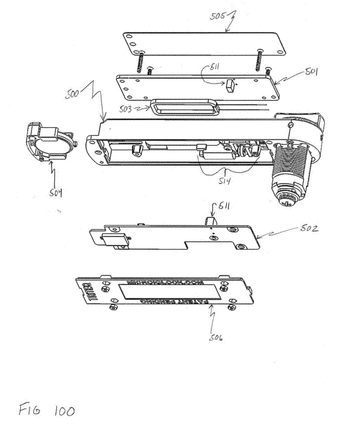
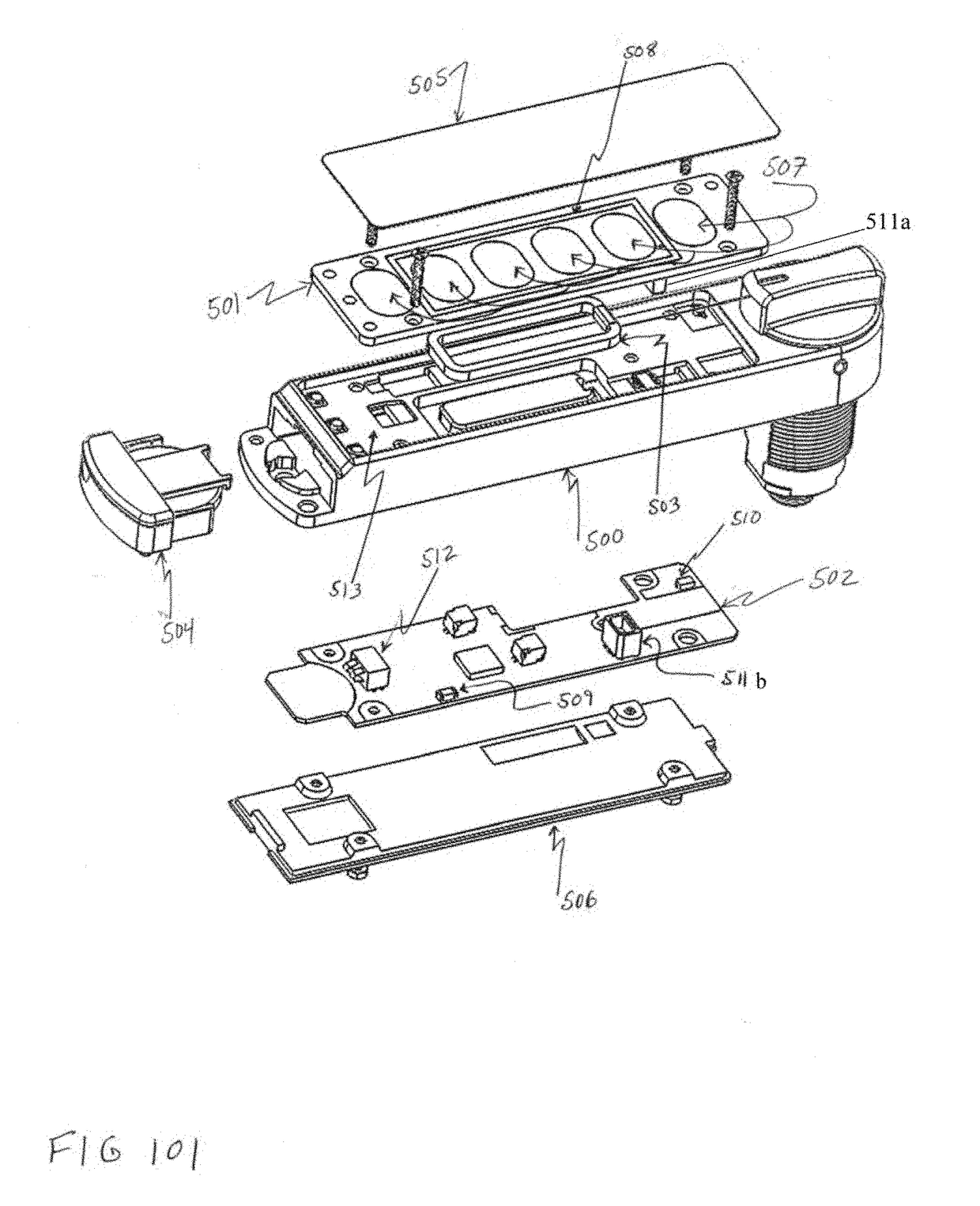
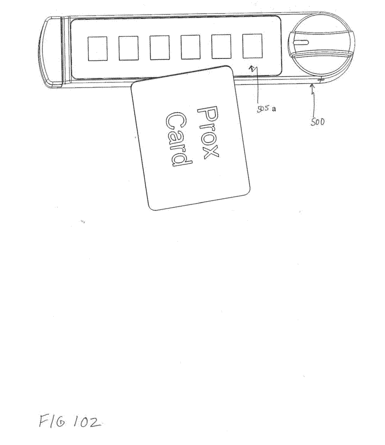
[0022]FIGS. 100, 101, 102 and 103 show external and exploded views of a housing 500 that encloses access control electronics comprising two circuit boards comprising radio frequency electronics 501 and 502, 125 KHz RFID antenna 503, battery and holder 504, keypad overlay 505, cover 506. FIG. 101 also shows proximity sensing pads 507, 13.56 MHz antenna 508 (routed around 4 sensor pads 507), Bluetooth antenna 509, latch position sensor 510, connector 511, and battery connector 512. Housing 500 is const...


PUM


Abstract

Access control electronics for wireless locks comprise one or more battery operated radios that receive access control codes. The wireless accessed locks locate the electronic components, circuits, sensors and antennas and many of the lock components away from the container being secured and closer to the operator / user. The disclosed access control electronics combine a proximity detection circuit comprising sensor pads and a capacitive sensing circuit and one or more short-range radio frequency antennas for reading RFID devices. The proximity sensor pads are in close proximity with the antennas, without the antennas interfering with the proximity sensing process, and the sensor pads to not attenuate the signals between the RFID devices and the antennas after the RFID devices are detected.

Description

RELATED APPLICATION[0001]This application relates to and claims priority to co-pending U.S. provisional patent application No. 62 / 547,584 titled “Access Control Electronics for Wireless Locks”, filed Aug. 18, 2017, the entire disclosure of which is incorporated herein by reference.TECHNICAL FIELD[0002]This application relates to access control electronics for wireless locks, and further relates to, incorporates certain aspects of and / or may be used in conjunction with the following pending U.S. patent applications, all of which are herein incorporated by reference: Ser. No. 14 / 719,218 entitled “Lock” and filed May 21, 2015 (Pub. No. 2015-0252591 A1 published Sep. 10, 2015); Ser. No. 14 / 728,996 entitled “Lock” and filed Jun. 2, 2015 (Pub No. 2016-0186463 A1 published 12-31-2015); Ser. No. 15 / 059,633 entitled “Lock” and filed Mar. 3, 2016 (Pub. No. 2016-0186463 A1 published Jun. 30, 2016); and Ser. No. 15 / 082,019 entitled “Lock” and filed Mar. 28, 2016 (Pub. No. 2016-0208518 A1 publis...

Claims


Application Information

Patent Timeline
IPC IPC(8): G07C9/00G06K17/00G06K19/07
CPCG07C9/00309G07C9/00166G06K17/0029G06K19/0723G07C2009/00769G07C9/0069Y10T70/7062G06K7/10128G06K7/10415G07C9/38
Inventor DENISON, WILLIAM D.ROATIS, CALIN V.MEIZELIS, THADDEUS A.MICHELSON, DANIEL R.RIBU, GABRIEL
Owner TRITEQ LOCK & SECURITY L L C
Why Eureka
Try Eureka