
Interposer substrate and method for manufacturing the same

Active Publication Date: 2019-03-07
PHOENIX PIONEER TECH
View PDF5 Cites 0 Cited by
  • Summary
  • Abstract
  • Description
  • Claims
  • Application Information

AI Technical Summary

Benefits of technology

The present patent is about a new interposer substrate and manufacturing method that improves strength and toughness. It does this by adding a phosphorus compound to the insulating protection layer, making it a thin and flexible material that prevents warping and other structural issues. Overall, this new substrate satisfies the need for thinness and variations in stress while maintaining excellent performance.

Problems solved by technology

However, the spacing of the logic package is usually in the scale of microns.
As a result, despite having a memory package of high line density, there is no logical package of the equivalent density that can be used to effectively produce an electronic product.
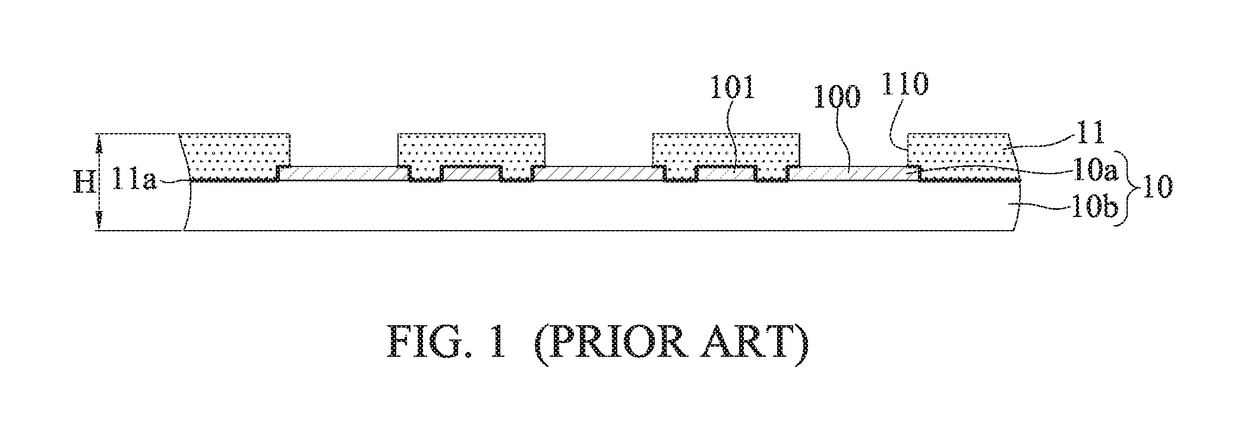
As a result, substrate warpage may occur when the interposer substrate 1 has shrinkage stress or structural asymmetries.
This causes the thickness H of the interposer substrate 1 to exceed 180 μm, resulting in failing to meet the requirement for thin interposer substrates.
However, this manufacturing process is complicated, and uneven coating often occurs, resulting in low reliability of the interposer substrate 1.

Method used


Image

  • Interposer substrate and method for manufacturing the same
  • Interposer substrate and method for manufacturing the same
  • Interposer substrate and method for manufacturing the same

Examples


Embodiment Construction

[0021]The present disclosure is described by the following specific embodiments. Those with ordinary skills in the arts can readily understand other advantages and functions of the present disclosure after reading the disclosure of this specification. The present disclosure may also be practiced or applied with other different implementations. Based on different contexts and applications, the various details in this specification can be modified and changed without departing from the spirit of the present disclosure.

[0022]It should be noted that the structures, ratios, sizes shown in the drawings appended to this specification are to be construed in conjunction with the disclosure of this specification in order to facilitate understanding of those skilled in the art. They are not meant, in any ways, to limit the implementations of the present disclosure, and therefore have no substantial technical meaning. Without affecting the effects created and objectives achieved by the present ...


PUM


Abstract

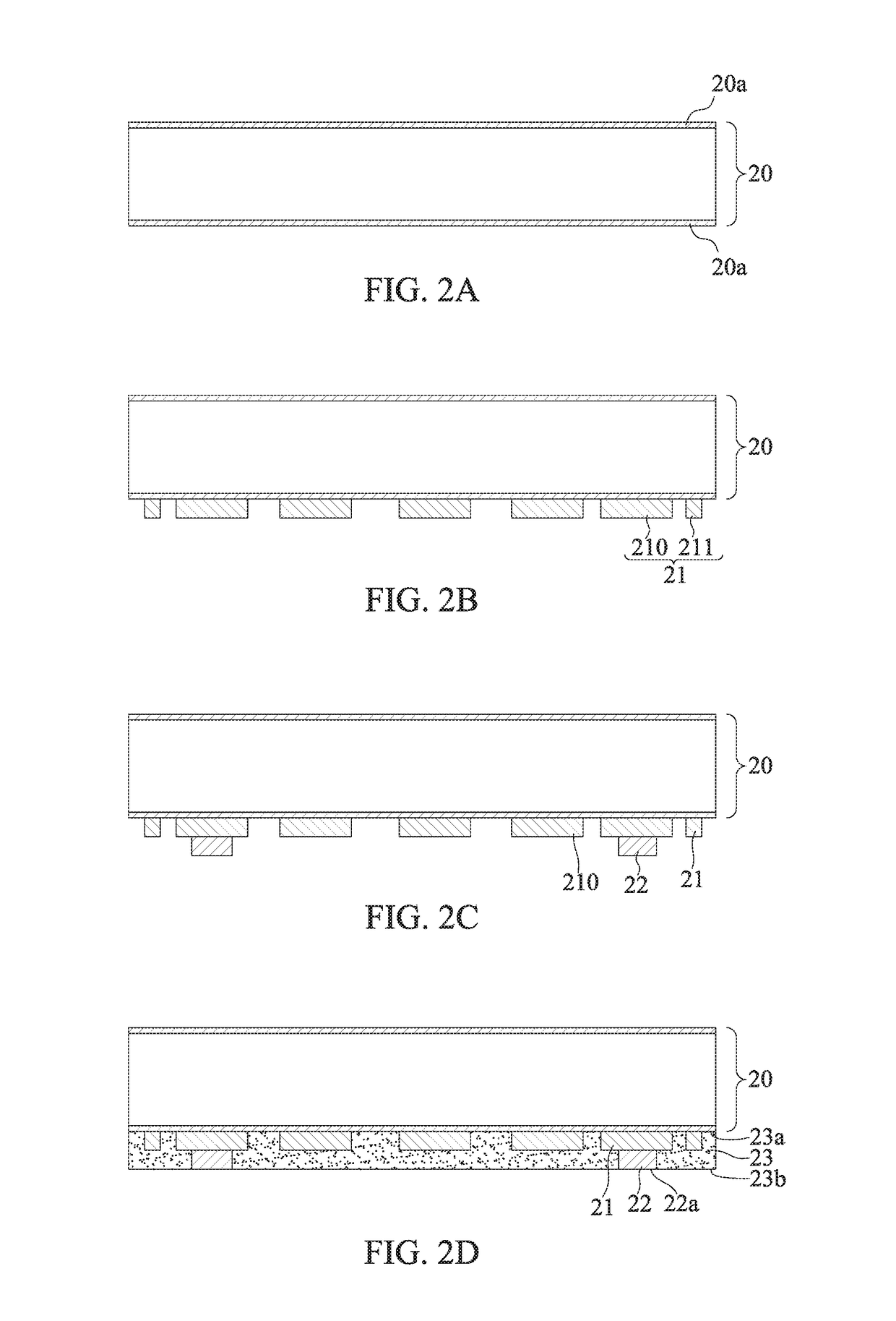
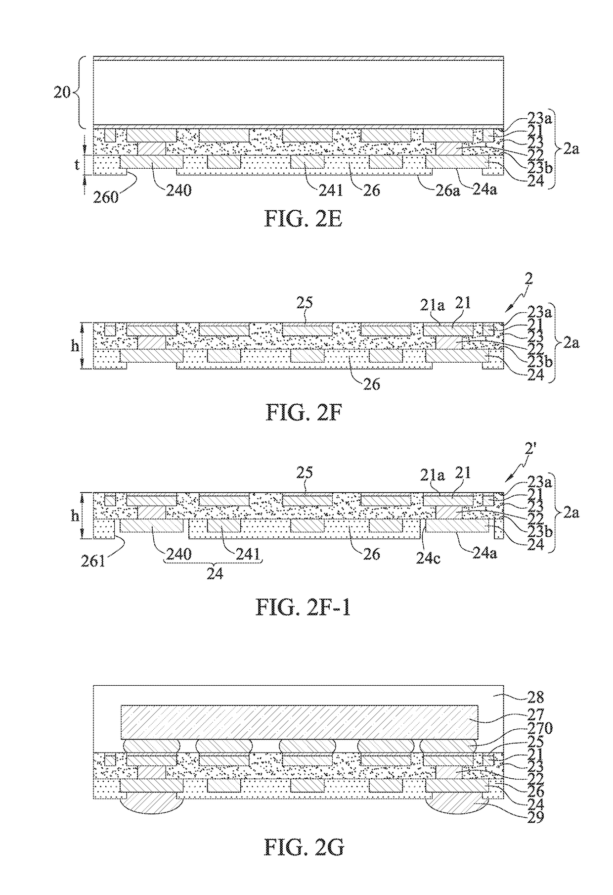
The disclosure provides an interposer substrate and a method for manufacturing the same. The method includes forming an insulating protection layer having a phosphorus compound on a substrate body, thereby providing toughness and strength as required when the thickness of the interposer substrate becomes too thin, and preventing substrate warpage when the substrate has a shrinkage stress or structural asymmetries.

Description

BACKGROUND1. Technical Field[0001]The present disclosure relates to interposer substrates, and, more particularly, to an interposer substrate suitable for a packaging process and a method for manufacturing the same.2. Description of Related Art[0002]Early packaging stack structure involves stacking a memory package (commonly known as a memory IC) on a logic package (commonly known as a logic IC) via a plurality of solder balls. With the rising demands for more compact and multi-functional electronic products, the wiring density of the memory package is getting higher, often down to the nanometer scale, so the spacing between contacts is increasingly becoming smaller. However, the spacing of the logic package is usually in the scale of microns. As a result, despite having a memory package of high line density, there is no logical package of the equivalent density that can be used to effectively produce an electronic product.[0003]In view of the above problem, an interposer substrate ...

Claims


Application Information

Patent Timeline
IPC IPC(8): H01L23/00
CPCH01L24/97H01L24/42H01L2924/051H01L2924/351H01L2224/73265H01L2224/48227H01L2924/181H01L2224/80904H01L24/16H01L24/48H01L2224/16227H01L24/08H01L2224/08225H01L23/49827H01L23/49816H01L23/145H01L2224/131H01L2924/014H01L23/498
Inventor HSU, SHIH-PINGHSU, CHE-WEICHANG, CHING-CHIEHTSENG, CHAO-CHUNG
Owner PHOENIX PIONEER TECH
Features
  • Generate Ideas
  • Intellectual Property
  • Life Sciences
  • Materials
  • Tech Scout
  • Unparalleled Data Quality
  • Higher Quality Content
  • 60% Fewer Hallucinations
Learn More