
Assistant Application for a Modular Control System

a technology of modular control system and assistant application, which is applied in the direction of electrical programme control, program control, instruments, etc., can solve the problems of not having as many databases and software applications, and the distribution control system is very complex and feature-rich, so as to facilitate the configuration and management of the modular control system and reduce the frequency

Active Publication Date: 2019-03-14
FISHER-ROSEMOUNT SYST INC
View PDF0 Cites 7 Cited by
  • Summary
  • Abstract
  • Description
  • Claims
  • Application Information

AI Technical Summary

Benefits of technology

The patent describes a modular control system that can operate in a standalone mode or as a node in a distributed control system. It includes a modular controller capable of executing control logic independently of other controllers. An assistant software application, called skid assistant or modular assistant, helps configure and manage the modular control system. The assistant can control the timing of providing a new configuration to the modular control system to reduce the frequency of accessing the system's memory. It also checks the coupling between the workstation and the modular control system at different stages to prevent erroneous back-up or communication. The technical effects of this patent are improved efficiency and reliability of the modular control system, as well as better protection of information exchanged between a distributed control system and the modular control system.

Problems solved by technology

In general, distributed control systems are very complex and feature-rich.
While more robust than a traditional PLC, the modular control system generally does not include as many features as a DCS, and not as many databases and software applications may be available for managing the modular control system.

Method used


Image

  • Assistant Application for a Modular Control System
  • Assistant Application for a Modular Control System
  • Assistant Application for a Modular Control System

Examples


Embodiment Construction

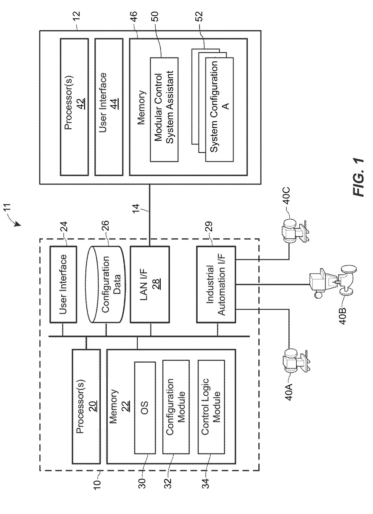
[0037]FIG. 1 illustrates an example a modular controller 10, which may operate in a skid-mounted system, coupled to a computer 12 via an Ethernet connection 14. The modular controller 10 includes one or more processors 20, for example, which can include general-purpose (e.g., CPU, GPU) or special-purpose (e.g., ASIC, FPGA) hardware. The one or more processors 20 are coupled to a memory module 22, a user interface 24, a local configuration database 26, a local area network interface 28, and an industrial automation interface 29.

[0038]The memory 22 stores an operating system 30. In some implementations, the operating system 30 is a real-time operating system such as QNX that allows the modular controller 10 to concurrently execute multiple services and applications. For example, a configuration module 32 can execute concurrently with a control logic module 34. The configuration module 32 can receive configuration data from the computer 12, store the received configuration data in the ...


PUM


Abstract

A method for efficiently managing configuration of modular control systems includes Detecting a communicative coupling between a workstation and a modular control system, determining whether an active project stored in a memory of the workstation matches a saved project stored in a memory of the modular control system, where each of the active project and the saved project includes a respective coordinated set of data for controlling operation of the modular control system, and when the active project and the saved project do not match, (i) determining whether the active project is correct for the modular control system, and (ii) when the active project is incorrect the modular control system, automatically providing, via an interactive user interface, a control for transferring at least a portion of the saved project from the memory of the modular control system to the active project in the memory of the workstation.

Description

CROSS-REFERENCE TO RELATED APPLICATIONS[0001]This application claims priority to provisional U.S. application Ser. Nos. 62 / 558,345 and 62 / 567,225 filed on Sep. 13, 2017 and Oct. 2, 2017, respectively, the entire disclosures of which are hereby expressly incorporated by reference herein.FIELD OF THE TECHNOLOGY[0002]This disclosure relates generally to using modular control systems such as skid-mounted systems in process control, in particular, to efficiently managing configuration of skid-mounted systems operating in standalone mode.BACKGROUND INFORMATION[0003]Modular control systems, used today in a variety of industries, are complete control systems that can provide specific functionality, such as boiling water, filtering liquids, or controlling heat exchange. A modular control system typically is implemented as a skid-mounted system, or simply “skid,” so called because the system is enclosed within a frame and is easily transported. A skid can be delivered to a factory as an integ...

Claims


Application Information

Patent Timeline
Patent Type & Authority Applications(United States)
IPC IPC(8): G05B23/02G05B19/042G06F3/0484G06F3/0482
CPCG05B23/0216G05B23/0213G05B19/0426G06F3/04847G06F3/0482G05B19/4185G05B2219/33139G05B19/042G05B19/418G06F8/65G06F8/71
Inventor JONES, AARON C.OTT, MICHAEL G.NAIDOO, JULIAN K.COLCLAZIER, DEBORAH R.JOHNSON, KAREN
Owner FISHER-ROSEMOUNT SYST INC
Learn More