Directional discharge wing pulley

a wing pulley and directional discharge technology, which is applied in the direction of conveyor parts, rollers, transportation and packaging, etc., can solve the problems of recirculation, wing fold-over failure of traditional straight wing pulleys, and pulleys that cannot be operated in one direction of rotation, so as to increase the efficiency of directional discharge wing pulleys

Active Publication Date: 2019-03-21
PUNCHING CONCEPTS
View PDF2 Cites 5 Cited by
  • Summary
  • Abstract
  • Description
  • Claims
  • Application Information

AI Technical Summary

Benefits of technology

[0008]The present invention provides a directional discharge wing pulley having a plurality of wings that discharge material in a single direction. In one embodiment, each directional discharge wing of the pulley is generally unobstructed from one end of the pulley to the opposite end. This design allows debris to be rapidly removed from the pulley in a single or primary direction...

Problems solved by technology

The traditional straight wing pulley breaks material loose from the backside of the belt through the impact of the wing tips on the belt, but the debris falls between the wings of the pulley, where it can becomes trapped and recirculates between the belt and pulley.
Additionally, traditional straight wing pulleys can have wing fold-over failures when heavy loads are applied due to the straight wings being perpendicular the direction of belt travel.
While the steep angle spiral assists by allowing debris to enter the pulley and slowly work outward, this does not align with m...

Method used


Image

  • Directional discharge wing pulley
  • Directional discharge wing pulley
  • Directional discharge wing pulley

Examples


Embodiment Construction

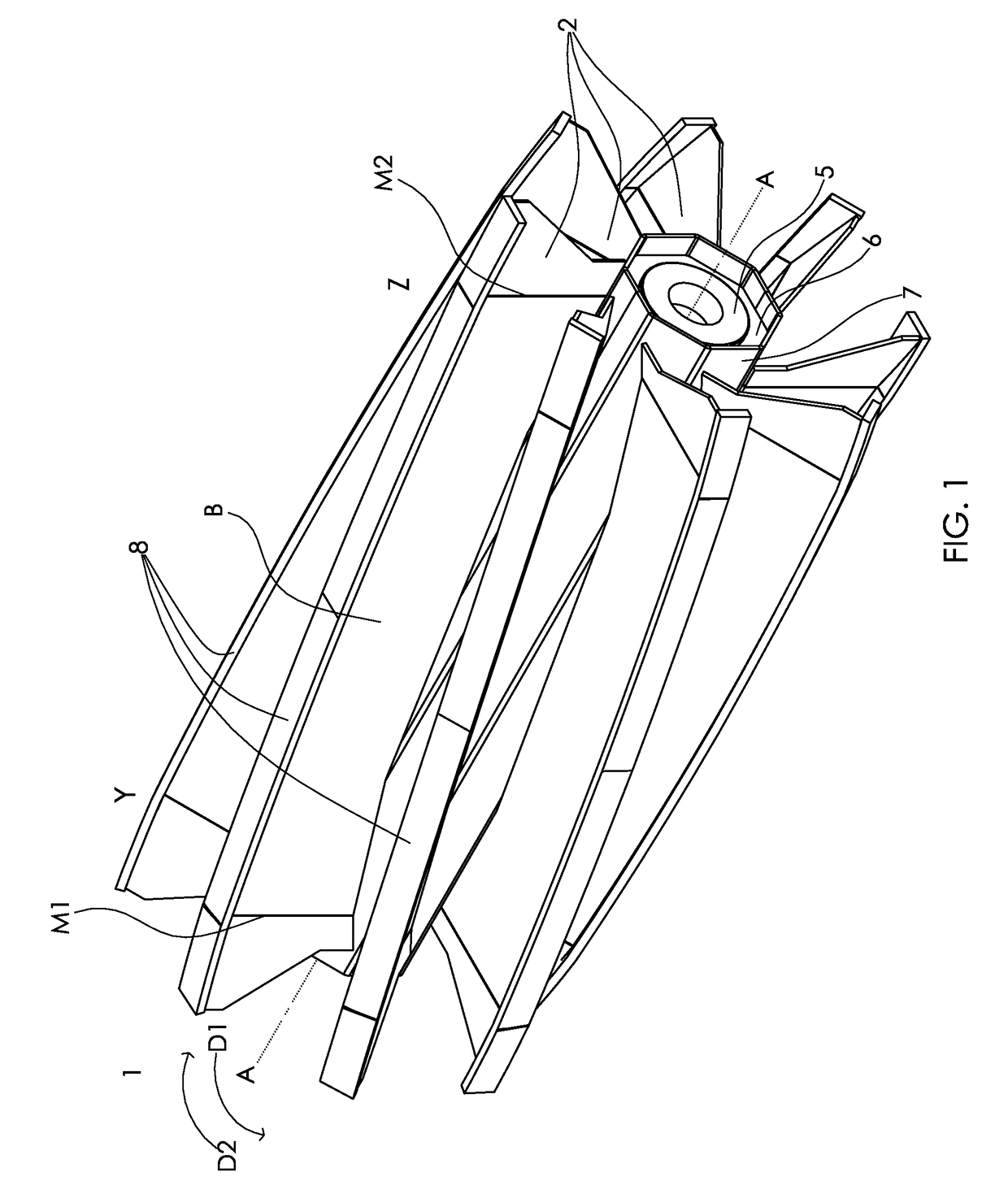
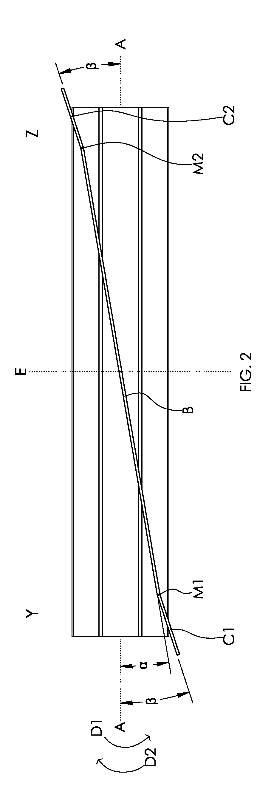
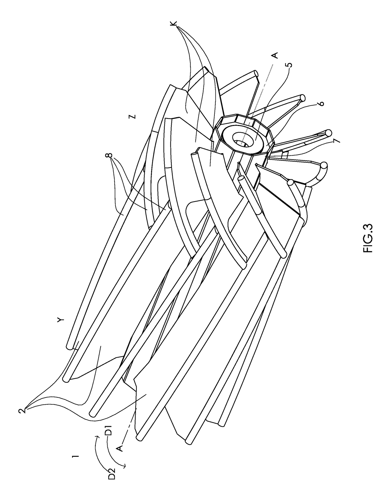
[0030]A directional discharge wing pulley (1) in accordance with one embodiment of the present invention is shown in FIGS. 1-11. The directional discharge wing pulley (1) is intended for use in supporting a conveyor belt in a wide range of conveyor systems. The directional discharge wing pulley (1) is well suited for non-drive locations of a conveyor system, such as an idler pulley or a tensioner pulley, but may be used as a drive pulley in drive applications. As a wing-type pulley, the discharge wing pulley (1) is a particularly beneficial where debris is present. While the directional discharge wing pulley (1) may be used to tension, drive or otherwise support the belt of a conveyor system, the primary distinguishing functions of this angled wing pulley are to provide enhanced cleanout in a single or primary direction while maintaining proper belt tracking and the ability to operate in reversing applications. When the directional discharge wing pulley (1) is used with deflectors (...


PUM


Abstract

A directional discharge wing pulley having a plurality of wings that discharge material in a single direction while properly tracking the conveyor belt. The directional discharge wing pulley may include a plurality of directional discharge wings, which are generally angled in a single or primarily in single direction across the entire face of the pulley. When pulley is operated a reverse rotation direction, the conveyor belt continues to properly track and the material is discharged in the opposite direction. The wings may have bends to create flat sections, or formed in a multiple arc pattern to create smoother changes in geometry or increased wing angle near the ends of the pulley, while generally maintaining a single direction wing through the entire pulley. Strengthening rib bends may be added near the end of a straight wing to add rigidity reducing the likelihood of wing fold over. The wings may include secondary wings, for example, in a Herringbone pattern. In some applications, the wings may include longitudinal or circumferential wing tips. In other applications, the wings may include a multi-start spiral.

Description

BACKGROUND OF THE INVENTION[0001]The present invention relates to conveyor belt pulleys, and more particularly, to self-cleaning wing pulleys that are suited for bulk material handling applications.[0002]In many types of conveyor applications, material can stick to or become entrapped behind the conveyor belt. When material is behind the conveyor belt, it is considered debris that must be displaced from the system for optimum conveyor belt traction and belt life.[0003]The use of traditional straight, steep angled spiral, or symmetrically opposite angled wing pulleys is common in a wide variety of bulk materials handling applications. All three of these pulleys are constructed from materials and thicknesses that are appropriate for the size and rigor of the final application.[0004]The traditional straight wing pulley is the original wing pulley. It is designed with plurality of radially spaced straight wings and wing tips that run the entire length of the pulley parallel to the centr...

Claims


Application Information

Patent Timeline
IPC IPC(8): B65G39/073B65G23/04
CPCB65G39/073B65G23/04B65G2201/04B65G2812/02148B65G2812/02168
Inventor KOWALSKI, NICHOLAS L.KONIECZNY, BRIAN J.GIES, MATTHEW L.SANDERSON, EDWARD E.
Owner PUNCHING CONCEPTS
Why Eureka
Try Eureka