Supercharge Your Innovation With Domain-Expert AI Agents!

Induction forming and curing of thermoset composite charges

a technology of composite charges and induction forming, which is applied in the field of induction tooling, can solve the problems of affecting the overall manufacturing time of the product, laying up complex cross-sections layer by layer, and separate forming and curing steps

Active Publication Date: 2019-03-28
THE BOEING CO
View PDF5 Cites 1 Cited by
  • Summary
  • Abstract
  • Description
  • Claims
  • Application Information

AI Technical Summary

Benefits of technology

The present patent provides an induction system for controlling the temperature and pressure of a thermoset composite charge during its formation and curing process. The system includes a tooling die and a flexible membrane, which is placed between the tooling die and a second tooling die. The flexible membrane is designed to receive pressure and conform the composite charge to the first tooling die. The system also includes a first and second smart susceptor material, which are placed within the die cavity and connected to the tooling dies. The first smart susceptor material has a higher Curie temperature than the second material, which allows for temperature control during the heating and curing process. The second smart susceptor material has a lower Curie temperature, which allows for pressure control during the process. The system can provide precise temperature and pressure control to improve the quality and efficiency of the thermoset composite charge process.

Problems solved by technology

However, laying up complex cross-sections layer by layer may take an undesirable amount of time.
Laying up complex cross-sections layer by layer may impact at least one of the amount of manufacturing time for a component, the amount of in-process flow time for a layup tool, or the amount of human operator time.
Separate forming and curing steps may impact overall manufacturing time by adding transfer processes.

Method used


Image

  • Induction forming and curing of thermoset composite charges
  • Induction forming and curing of thermoset composite charges
  • Induction forming and curing of thermoset composite charges

Examples


Embodiment Construction

[0024]The illustrative embodiments recognize and take into account one or more different considerations. For example, the illustrative embodiments recognize and take into account that current processing systems for complex small thermoset components require undesirable amounts of labor for hand lay-up and curing. The illustrative embodiments recognize and take into account that heated presses / ovens operating at separate temperatures for forming and curing requires multiple set-ups and processing runs.

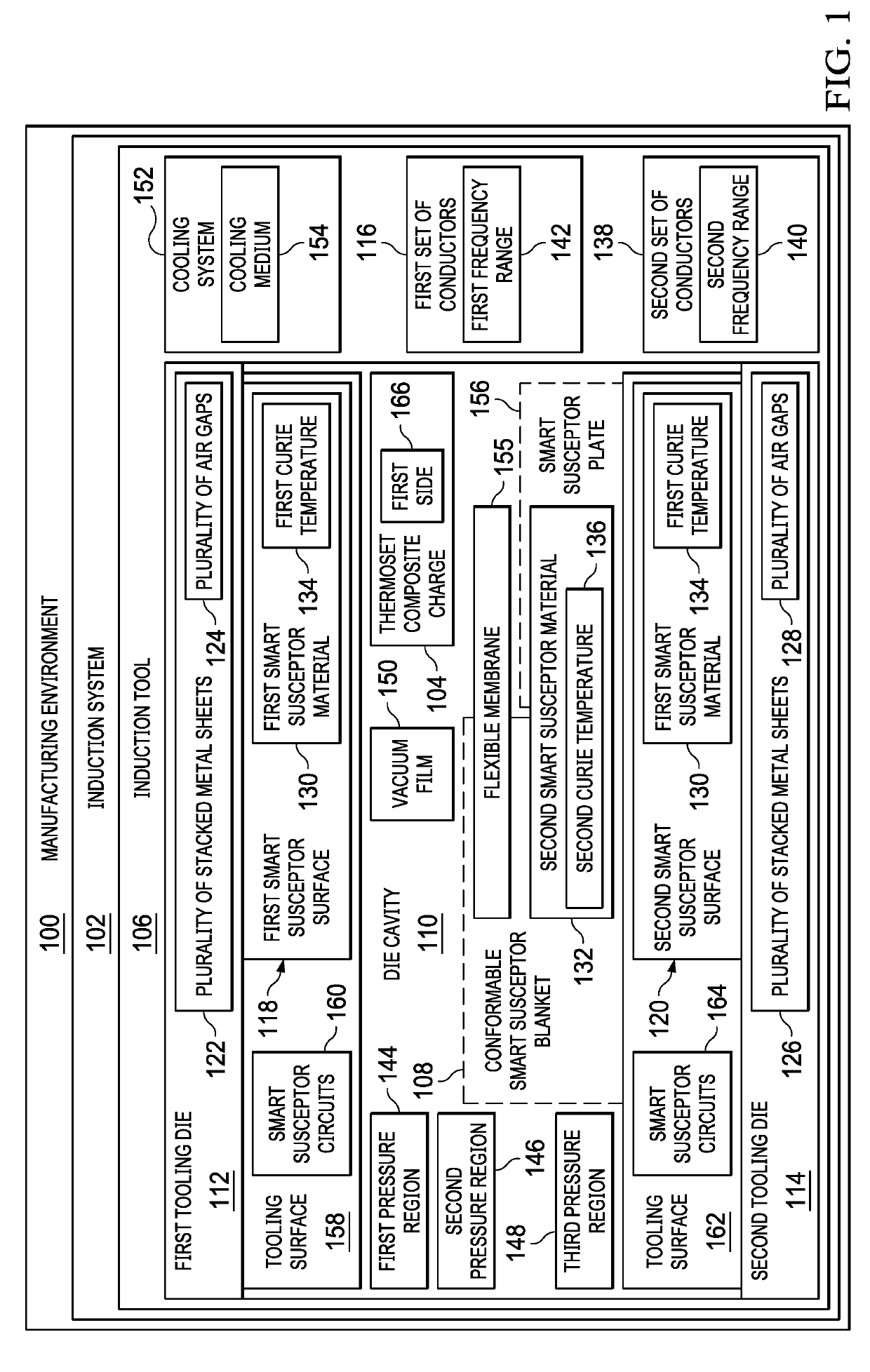
[0025]Referring now to the figures and, in particular, with reference to FIG. 1, an illustration of a block diagram of a manufacturing environment is depicted in accordance with an illustrative embodiment.

[0026]Manufacturing environment 100 includes induction system 102 for forming and curing thermoset composite charge 104. Induction system 102 is configured to provide temperature and pressure control for forming and curing of thermoset composite charge 104.

[0027]In one illustrative exa...


PUM

PropertyMeasurementUnit
frequencyaaaaaaaaaa
frequencyaaaaaaaaaa
temperatureaaaaaaaaaa

Abstract

A first tooling die and a second tooling die are movable with respect to each other. The first tooling die and the second tooling die form a die cavity. The first tooling die and the second tooling die comprise a plurality of stacked metal sheets. A plurality of air gaps is defined between adjacent stacked metal sheets. A first smart susceptor material is within the die cavity and connected to the first tooling die. The first smart susceptor material has a first Curie temperature. A second smart susceptor material is within the die cavity and associated with the second tooling die. The second smart susceptor material has a second Curie temperature lower than the first Curie temperature. A flexible membrane is between the second tooling die and the first smart susceptor material. The flexible membrane is configured to receive pressure.

Description

BACKGROUND INFORMATION1. Field[0001]The present disclosure relates generally to induction tooling, and more specifically, to induction tooling for performing manufacturing operations on thermoset composite charges. Yet more specifically, the present disclosure relates to an induction system configured to both form and cure a thermoset composite charge.2. Background[0002]Composite materials are tough, light-weight materials created by combining two or more functional components. For example, a composite material may include reinforcing fibers bound in a polymer resin matrix. The fibers may be unidirectional or may take the form of a woven cloth or fabric. The fibers and resin are arranged and cured to form a composite material.[0003]Thermoset composite materials are composite materials having a resin that cures upon application of at least one of temperature or pressure, thus forming the final composite structure. Thermoset composite materials are shaped prior to curing.[0004]In manu...

Claims


Application Information

Patent Timeline
Patent Type & Authority Applications(United States)
IPC IPC(8): B29C33/06B29C70/46
CPCB29C33/06B29K2101/10B29C70/46B29C70/34B29C70/54B29C70/44B29C35/0805B29C2035/0811B29C2035/0816B30B5/02
Inventor MATSEN, MARC R.LUCHINI, TIMOTHY J.VOSS, BRET A.HOTTES, CHRISTOPHER J.
Owner THE BOEING CO
Features
  • R&D
  • Intellectual Property
  • Life Sciences
  • Materials
  • Tech Scout
  • Unparalleled Data Quality
  • Higher Quality Content
  • 60% Fewer Hallucinations
Learn More