Universal id system and methods and biometric information

a biometric information and universal identification technology, applied in the field of devices authentication, can solve the problems of no one to call to replace lost or stolen biometric information, single online personas that do not truly reflect how entities are, and many entities that are simply not worth the expense and maintenance of many entities

Inactive Publication Date: 2019-03-28
OURARING INC
View PDF12 Cites 11 Cited by
  • Summary
  • Abstract
  • Description
  • Claims
  • Application Information

AI Technical Summary

Benefits of technology

[0009]Another object of the present invention is to provide systems, methods and devices that reduce the problem of biometric information of an entity being stolen.
[0010]Yet another object of the present invention is to provide systems, methods and devices that do not store an entities biometric information on a centralized server and reduces or eliminates biometric information being stolen by hackers.

Problems solved by technology

Besides the security and data control / privacy concerns this raises, such single online personas do not truly reflect how entities behave or act in the real, physical world.
Other factors that have prevented universal authentication from widespread adoption include generally a lack of motivation from manufacturers and companies to create their own apps, portals, back-end infrastructure, secure element hardware, and so on, that would be needed to implement a signal or signal framework with their customers.
Again, this leads to a siloed approach that is simply not worth the expense and maintenance for many entities.
However, when biometric information is stolen there is no one to call to replace the lost or stolen biometric information.
This is a major problem when electronic devices, security cameras, public infrastructure, machines, consumer electronics and websites and the like collect and store this type of information creating millions of points of attack for hackers to steal our personal biometric data.

Method used


Image

  • Universal id system and methods and biometric information
  • Universal id system and methods and biometric information
  • Universal id system and methods and biometric information

Examples


example 1

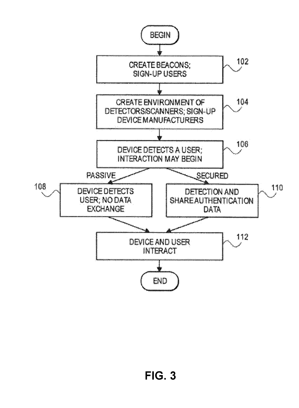
[0071]FIG. 3 is an example of how an entity operates with the system 10. At step 102 an entity operates as a transmitter and moves around in a physical space. At step 104 an environment or space in which an electronic device operates is created. At step 106 the electronic device of a first entity detects a signal from system 10 in response to an initial interaction between the first entity electronic device and a second entity electronic device.

[0072]The initial interaction can be a passive interaction shown in step 108. Here the first party electronic device detects the presence of a signal. The device may not determine the identity of the entity, that is, the entity remains anonymous. In another passive mode embodiment, the entity may be identified but only in by back-end or the cloud and not on the electronic device itself. As a non-limiting example, the server may be accessible without a Network System connection or being online (e.g., via Ethernet, Zigbee, and the like). This p...

example 2

[0074]FIG. 4 illustrates a non-limiting example of a physical environment showing different types of electronic devices with signals. As a non-limiting example, the electronic device accesses back-end or the cloud with a server. As a non-limiting example, the server has numerous roles, such as authenticating the entity and maintaining access-control lists for signals and electronic devices.

example 3

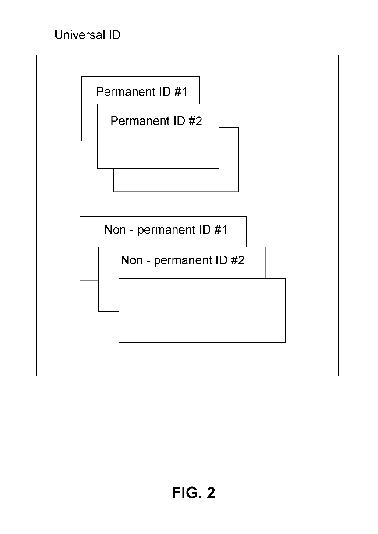
[0075]FIG. 5 is a block diagram showing three components used for the Universal ID.

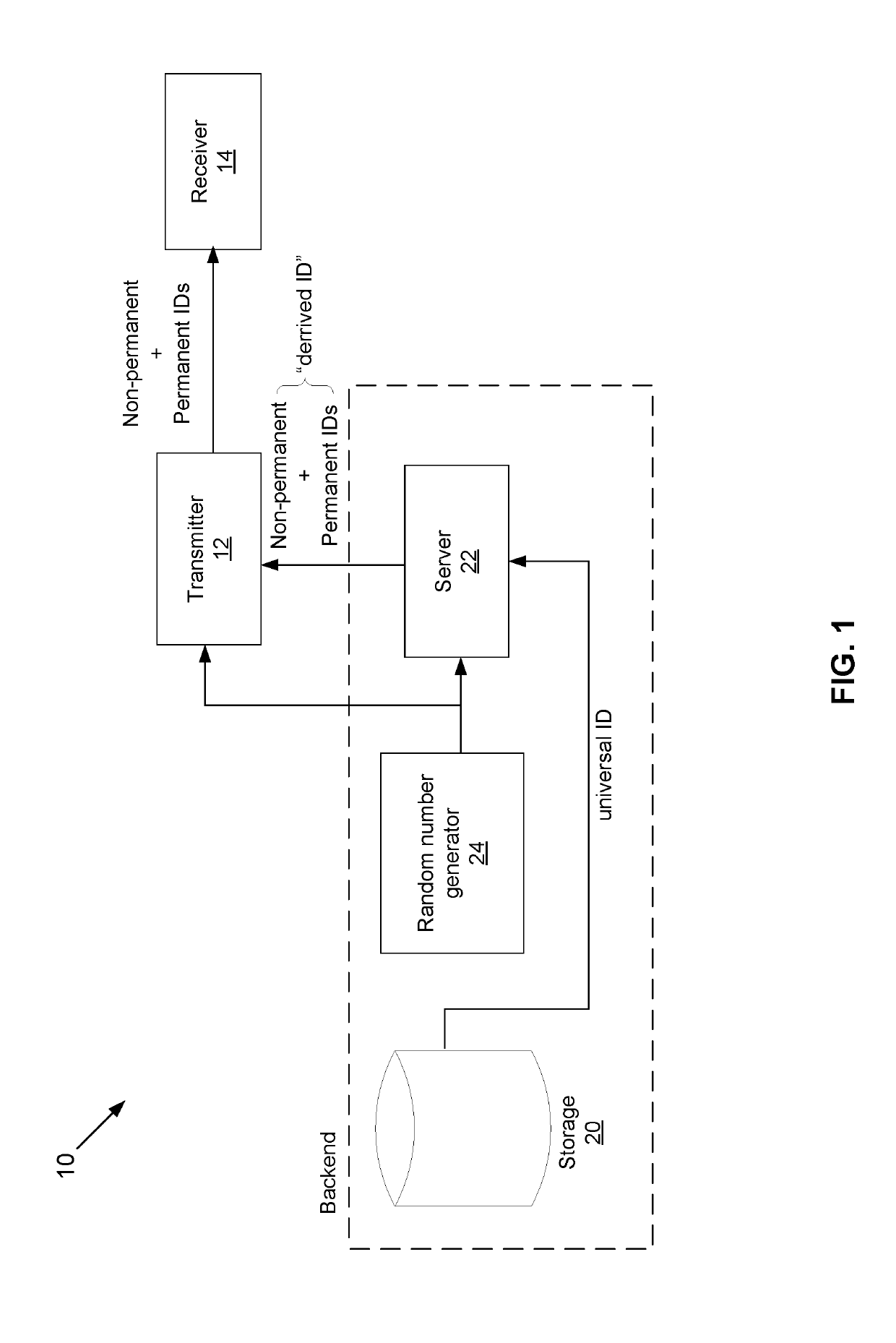
[0076]An electronic device 306 acts as the detector or scanner in the environment. As described, device 306 can take the form of one of a multitude of objects as previously disclosed. Nearly all have a software module 308. Software module 308, as well as module 304, performs many of the operations described in the flow diagrams below. In some embodiments, device 306 may also have a hardware component 310, such as a Bluetooth component or other hardware needed for connectivity with signal 302 or with a dedicated server, the other component in FIG. 5.

[0077]A server 312 may have extensive software modules, such as the universal signal app 316, and at least one database 314 which stores data on electronic device, entities, access control tables, and a wide variety of data needed to implement the universal signal environment of the present invention.


PUM


Abstract

A method is provided of conducting an interaction between a first entity and a second entity. A Universal ID system includes a front end with a transmitter, a receiver coupled to the transmitter and at least one passive filter coupled to the transmitter. The front-end is coupled to at least one of a back-end or a cloud system. Each of the back-end and the cloud system includes: storage; server; a Universal ID character generator device that generates portions of the Universal ID. In response to an interaction between the first entity and a second entity he transmitter transmits a signal for all or a portion of a first entity Universal ID that includes non-permanent IDs and permanent IDs. The Universal ID includes and / or is layered with biometric identifiers of the first entity. The signal includes a plurality of authentications with identifiers. Each of an authentication associated with a different second entity. The first party Universal ID is used with a plurality of electronic devices that each have a different first entity authentication from the Universal ID with each of a different electronic device requiring a first entity authentication to gain access to each of an electronic device of the plurality of electronic devices. The signal provides an authentication of the Universal ID to a second entity and is done passivity where the first entity takes no action for the first entity Universal ID signal to be emitted, and for an interaction to be sensed and acted on by an action, in response to the interaction the second entity creates an action that causes a physical change in a hardware component of a second entity electronic device.

Description

CROSS-REFERENCE TO RELATED APPLICATIONS[0001]This application is a Continuation-In-Part of Ser. No. 16 / 129,901, filed on Sep. 13, 2018, which is a Continuation-In-Part of Ser. No. 16 / 129,859, filed on Sep. 13, 2018, which claims priority from U.S. Provisional Patent Application No. 62 / 685,292, filed on Jun. 15, 2018, which is incorporated herein by reference.BACKGROUNDField of the Invention[0002]This invention is directed to authentications for devices, and more particularly to systems, devices, methods that provide a Universal ID / Identification without centrally or locally storing an entities biometric information on a third-party infrastructure.Description of the Related Art[0003]Current methods to create a Universal Identification (ID) signal for an entity have involved frameworks or underlying models in which the burden of implementing the signal-broadcasting it and ensuring that devices detect it and this rests on the entity. This task of creating a personal signal or what is s...

Claims


Application Information

Patent Timeline
Patent Type & Authority Applications(United States)
IPC IPC(8): H04L29/06
CPCH04L63/0861H04L63/0876G06F21/32G06F21/34H04L63/10H04W12/02H04W12/06
Inventor MARS, DENISRATNER, SIMON
Owner OURARING INC
Why Eureka
Try Eureka