Diagnostic imaging system
- Summary
- Abstract
- Description
- Claims
- Application Information
AI Technical Summary
Benefits of technology
Problems solved by technology
Method used
Image

Examples
first embodiment
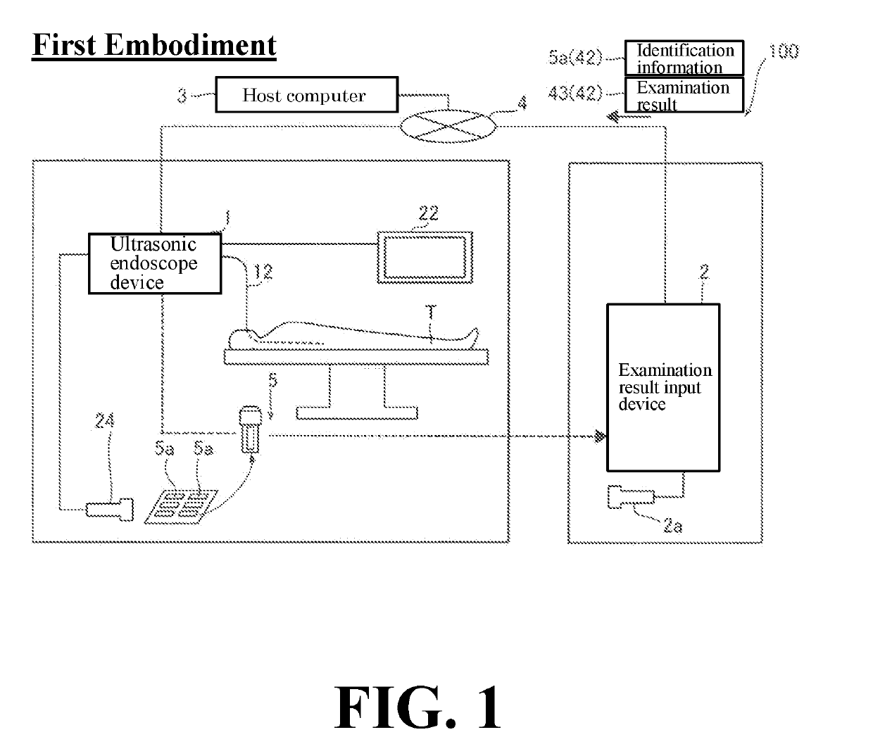
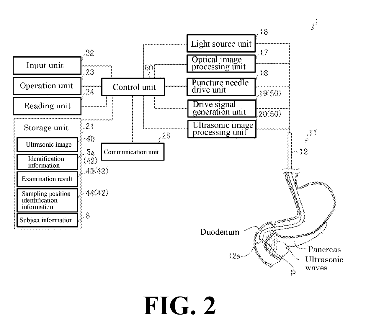
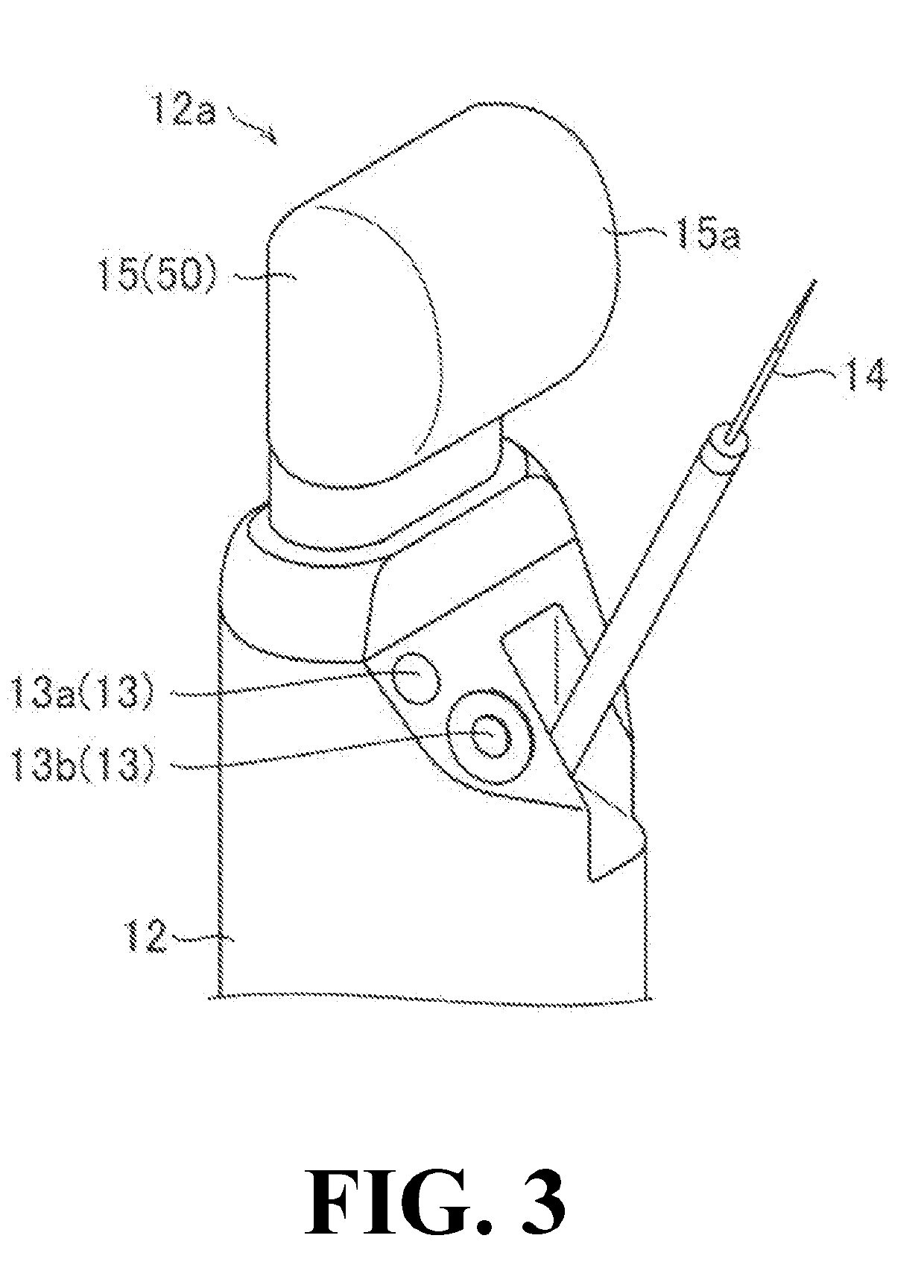
[0030]With reference to FIG. 1 to FIG. 5, the configuration of the diagnostic imaging system 100 according to the first embodiment of the present invention will be described.
[0031]As shown in FIG. 1, the diagnostic imaging system 100 is a system for associating an ultrasonic image 40 capable of identifying a sampling position P when a specimen 90 is sampled from a subject T and information for identifying a specimen 90 (hereinafter referred to as “specimen identification information 42”). That is, the diagnostic imaging system 100 is configured to associate the specimen 90 sampled from the subject T with the ultrasonic image 40 in which the sampling position P of the specimen 90 is distinguishably displayed by the specimen identification information 42.
[0032]The subject T is a subject to be subjected to a diagnosis of diseases, and the specimen 90 for diagnosis is sampled from the subject T by a doctor, etc. The subject T includes humans and other animals.
[0033]The specimen 90 inclu...
second embodiment
[0078]Next, with reference to FIG. 7 to FIG. 10, the configuration of the diagnostic imaging system 200 according to a second embodiment of the present invention will be described. In the second embodiment, the description is directed to the case in which the ultrasonic image 240 is captured from the outside (in vitro) of the subject T and the workstation 207 associates the specimen identification information 42 with the ultrasonic image 240. In the second embodiment, an example in which a tissue piece of a breast of a subject T is obtained as a specimen 90 will be explained. The same reference numerals are allotted to the same configurations as those of the first embodiment, and the description thereof will be omitted.
[0079]The diagnostic imaging system 200 of the second embodiment is provided with an ultrasonic imaging device 201, an examination result input device 2, a host computer 3, and a workstation 207.
(Configuration of Ultrasonic Imaging Device)
[0080]As shown in FIGS. 7 and...
modified embodiment
[0095]It should be understood that the embodiments disclosed here are examples in all respects and are not restrictive. The scope of the present invention is shown by the scope of the claims rather than the descriptions of the embodiments described above, and includes all changes (modifications) within the meaning of equivalent and the scope of claims.
[0096]For example, in the first embodiment, an example in which the diagnostic imaging system 100 is configured by the ultrasonic endoscope device 1, the examination result input device 2, and the host computer 3 is described. Further, in the first embodiment described above, an example in which the diagnostic imaging system 200 is configured by the ultrasonic imaging device 201, the examination result input device 2, the host computer 3, and the workstation 207, but the present invention is not limited thereto. In the present invention, the system configuration of the diagnostic imaging system is not limited to the aforementioned embo...
PUM
 Abstract
Description
Claims
Application Information
 - R&D Engineer
- R&D Manager
- IP Professional
- Industry Leading Data Capabilities
- Powerful AI technology
- Patent DNA Extraction
Browse by: Latest US Patents, China's latest patents, Technical Efficacy Thesaurus, Application Domain, Technology Topic.
© 2024 PatSnap. All rights reserved.Legal|Privacy policy|Modern Slavery Act Transparency Statement|Sitemap