
Wing or blade design for wingtip device, rotor, propeller, turbine, and compressor blades with energy regeneration

a technology of wingtip and energy regeneration, which is applied in the direction of propellers, engines, and influencers by generating vortices, can solve the problems of smaller strength of vortices in gaps, and achieve the effects of reducing the strength of vortices, reducing overall drag, and increasing overall li

Inactive Publication Date: 2019-04-04
MBODJ PAPA ABDOULAYE
View PDF11 Cites 3 Cited by
  • Summary
  • Abstract
  • Description
  • Claims
  • Application Information

AI Technical Summary

Benefits of technology

The present invention introduces a new design of wings, blades, or paddles for airplanes, boats, vehicles, and machines that use fluids. This design has low aspect ratio wings placed in parallel with gaps between them, which are shaped to slow down or speed up the fluid in a way that reduces the energy lost during the process. The gaps between the wings create a synergistic effect that increases liftoff, decreases drag, and makes vehicles more efficient. This design can be used in various applications such as wings, wingtips, propellers, wind turbines, and compressors.

Problems solved by technology

Even if the small aspect ratio makes those wings inefficient, the strength of the vortices is smaller in the gaps.

Method used


Image

  • Wing or blade design for wingtip device, rotor, propeller, turbine, and compressor blades with energy regeneration
  • Wing or blade design for wingtip device, rotor, propeller, turbine, and compressor blades with energy regeneration
  • Wing or blade design for wingtip device, rotor, propeller, turbine, and compressor blades with energy regeneration

Examples


Embodiment Construction

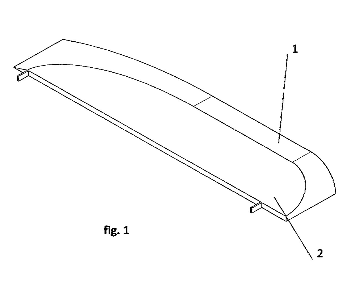
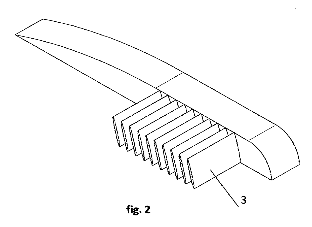
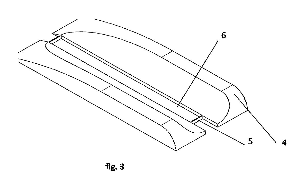
[0028]As shown in the drawings: The 1 corresponds to the low aspect ratio wing. The 2 corresponds to the gap that is shaped to decelerate the fluid and / or accelerate the fluid by varying the cross-sectional area. The 3 corresponds to the smaller wings that are placed in the gaps to harness the energy and produce forces. The 4 corresponds to the low aspect ratio wing. The 5 corresponds to a strut that connects adjacent low aspect ratio wings and takes the bending loads. The 6 corresponds to the gap that is shaped to decelerate the fluid and / or accelerate the fluid by varying the cross-sectional area. The 7 corresponds to the smaller wings that are placed in the gaps to harness the energy and produce forces. The 8 corresponds to a vortex generator to make the flow in the gap turbulent to keep the boundary layer attached. The 9 and 10 correspond to the small holes placed in those low aspect ratio wings through which hot gas or fuel mixture can be expelled. The holes are positioned to a...


PUM


Abstract

The new wing or blade design for wingtip device, rotor, propeller, turbine, and compressor blades with energy regeneration can be used to generate lift, propel vehicles more efficiently, compress fluids more efficiently, harness energy more efficiently. This system can be used as a wing, as a wingtip device, as a propeller for aircraft or boats or any vehicle moving through a fluid, in a compressor, as a rotor for wind turbine or helicopter, in a gas turbine. The new wing or blade design for wingtip device, rotor, propeller, turbine, and compressor blades with energy regeneration is a series of low aspect ratio wings placed in parallel with gaps between them connected by smaller wings that are placed in the gaps to harness the energy and produce forces; the gaps are shaped to decelerate the fluid and / or accelerate the fluid by varying the cross-sectional area of the gaps. Even if the small aspect ratio makes those wings inefficient, the strength of the vortices is smaller in the gaps.

Description

BACKGROUND OF THE INVENTION[0001]It is known that up to now lift generation surfaces as wings exist that although fulfilling the same function as the new wing or blade design for wingtip device, rotor, propeller, turbine, and compressor blades with energy regeneration, which is the subject of the invention, exhibit a certain number of technical problems which are among others: the strong wingtip vortices that are the source of induced drag and represent an issue for aviation safety; the lower efficiency of existing propeller or compressor or rotor.[0002]The aspect ratio of a wing is defined as the span length divided by the wing area to the square. A golden rule in aerodynamics is to have the highest aspect ratio for maximum efficiency. By increasing the span and keeping the same area, the wingtip vortices are reduced. Wingtip vortices are a primary source of drag, particularly at low speed and high wing loading.[0003]This invention called New wing, or blade design for wingtip devic...

Claims


Application Information

Patent Timeline
IPC IPC(8): F04D27/00B64C3/00B64C23/06B64C11/18B63H1/26B64C27/46F04D29/38F04D29/30F04D29/54F04D29/44F03D1/06F03D7/02
CPCF04D27/002B64C3/00B64C23/069B64C11/18B63H1/26B64C27/463F04D29/388F04D29/30F04D29/542F04D29/444F03D1/0675F03D7/0236F05B2260/507B64C11/20F03D7/022F04D27/0246F04D29/284F04D29/324F04D29/544F04D29/666F05B2240/307Y02E10/72F01D5/146
Inventor MBODJ, PAPA ABDOULAYE
Owner MBODJ PAPA ABDOULAYE
Learn More