Ac-dc converter

a converter and current waveform technology, applied in the direction of electric variable regulation, process and machine control, instruments, etc., can solve the problems of increasing the distortion of current waveform, and achieve the effects of improving efficiency, reducing resistive loss, and improving power factor

Inactive Publication Date: 2019-04-04
FUJI ELECTRIC CO LTD
View PDF0 Cites 5 Cited by
  • Summary
  • Abstract
  • Description
  • Claims
  • Application Information

AI Technical Summary

Benefits of technology

[0035]The present invention makes it possible to improve power factor without using voltage-dividing resistors to detect the AC power supply voltage or a rectified voltage thereof, thereby making it possible to improve efficiency by reducing resistive loss.
[0036]Moreover, the present invention does not rely on changing the amplitude of the carrier signal, and therefore there is no risk, unlike in Patent Document 1, that the current waveform is affected by noise due to the amplitude of the carrier signal becoming small. In other words, in the present invention, controlling the semiconductor switching device such that the duty cycle thereof is proportional to the detected value of the rectified current makes it possible to improve the power factor by controlling the AC input current to be a sine wave having the same phase as the AC input voltage.

Problems solved by technology

Meanwhile, the PFC circuit of Patent Document 1 as illustrated in FIGS. 4 and 5 does not use a rectified voltage Vr for control purposes, thereby making it possible to avoid occurrence of standby power due to the voltage-dividing resistors, which is one disadvantage of the scheme described in Patent Document 2.
However, when the amplitude of the carrier signal becomes small, the effects of noise become more prominent when performing PWM operations, which results in increased distortion of the current waveform.

Method used


Image

  • Ac-dc converter
  • Ac-dc converter
  • Ac-dc converter

Examples


Embodiment Construction

[0046]An embodiment of the present invention will be described with reference to figures.

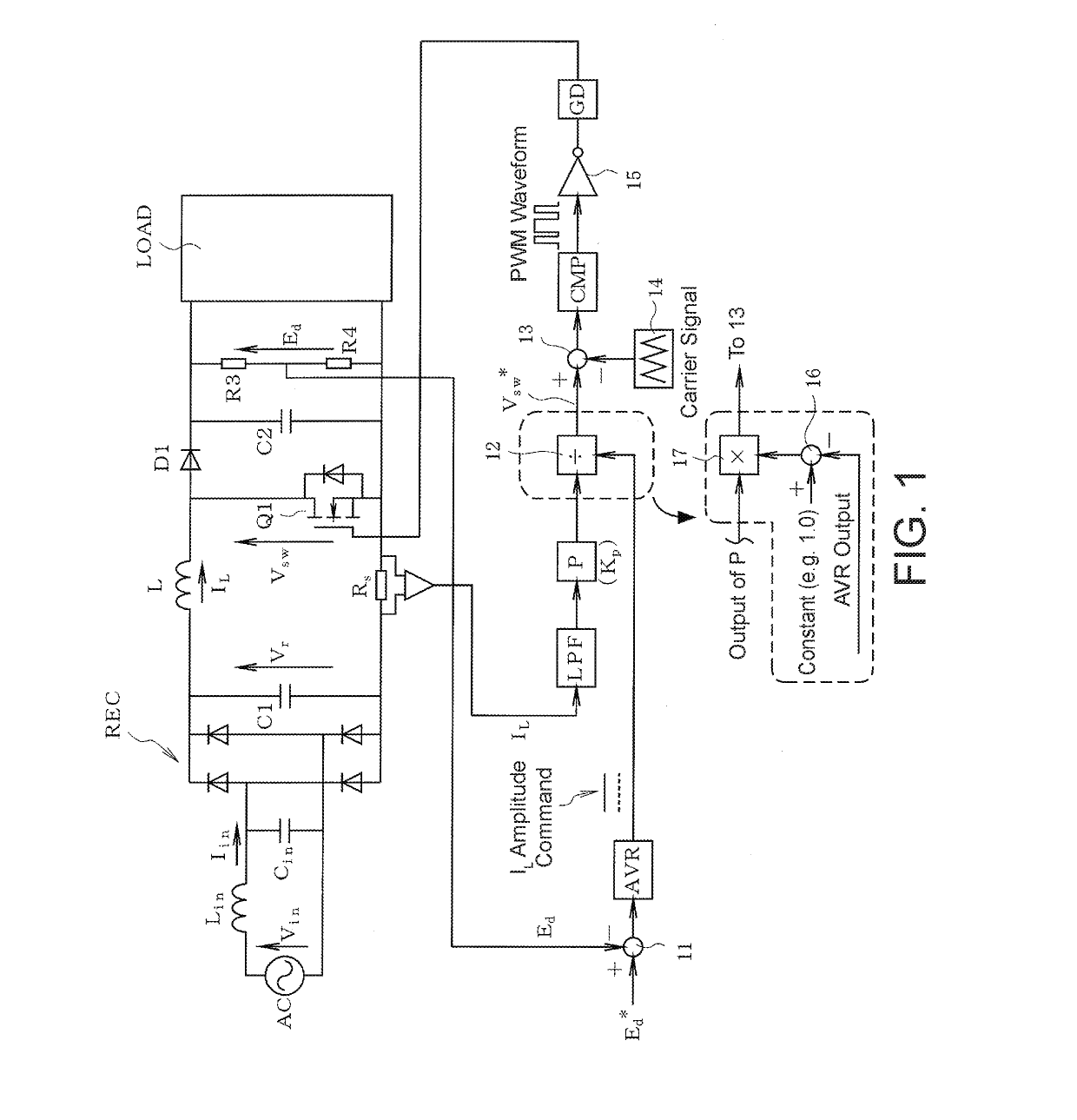
[0047]FIG. 1 is a block diagram of a PFC circuit for use as an AC-DC converter according to the embodiment of the present invention. The configuration of a main circuit in FIG. 1 is the same as in FIG. 8 except in that the voltage-dividing resistors R1 and R2 are removed. In other words, in the main circuit in FIG. 1, both terminals of an AC power supply (a commercial power supply) AC are connected, via an input filter constituted by a reactor Lin and a capacitor Cin, to a diode rectifier circuit REC.

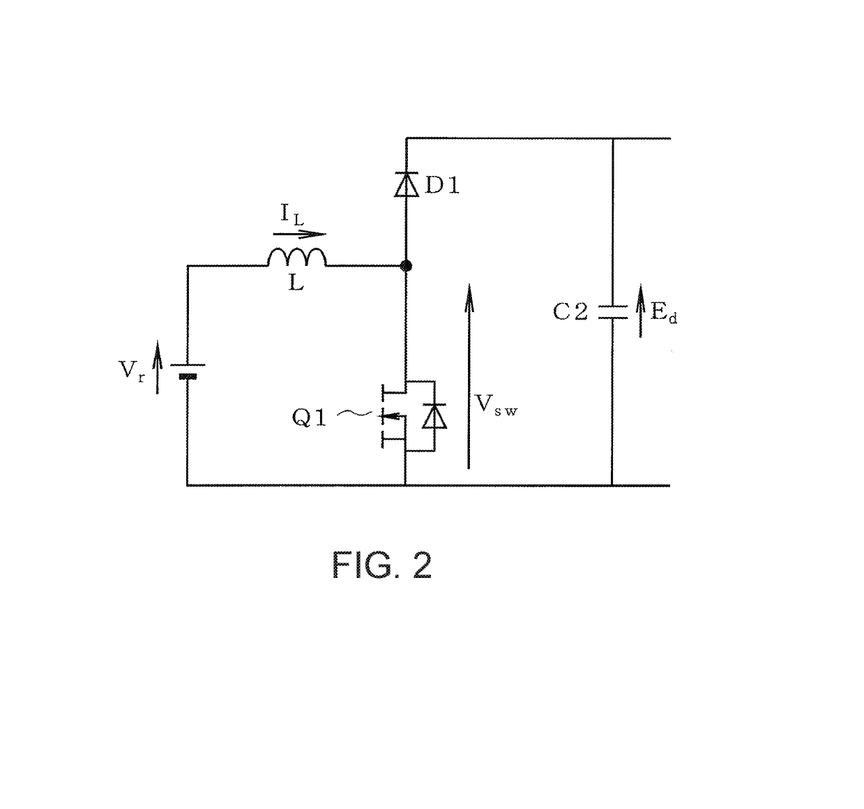
[0048]A capacitor C1 is connected between the positive and negative output terminals of the diode rectifier circuit REC, and a reactor L and a semiconductor switching device Q1 such as a MOSFET are connected in series to the both terminals of the capacitor C1. Moreover, a diode D1 and a capacitor C2 are connected in series to the both terminals of the semiconductor switching device Q1. A series circ...


PUM


Abstract

An AC-DC converter that converts a rectified voltage of an AC power supply AC to a DC output voltage by switching ON and OFF a switching device and controls the switching device by using a command value for and a detected value of the DC output voltage as well as a detected value of a reactor current includes: a current sense resistor and a low-pass filter for detecting a rectified current; a proportional controller that multiplies the detected value of the rectified current by a prescribed gain; an output voltage command calculator such as a divider that calculates an output voltage command for the switching device on the basis of an output of the proportional controller; and a circuit that compares the output voltage command to a carrier signal in order to generate a gate signal for the switching device, wherein the prescribed gain is effectively adjusted on the basis of a difference signal between a command value for and a detected value of the DC output voltage.

Description

BACKGROUND OF THE INVENTIONTechnical Field[0001]The present invention relates to an AC-DC converter such as a so-called power factor correction (PFC) circuit and to a technology for improving power factor (input power factor) by controlling an AC input current to be a sine wave having the same phase as an AC input voltage.Background Art[0002]FIG. 4 illustrates a PFC circuit described in Patent Document 1 which is driven using a one-cycle power factor control scheme as described below. In FIG. 4, REC is a diode rectifier circuit, L is a reactor, 100 is an integrated circuit, 120 is a voltage conversion circuit, 130 is a voltage-dividing circuit, Q1 is a semiconductor switching device such as a MOSFET, and Rs is a current sense resistor.[0003]The switching device Q1 is driven by a gate signal output from a terminal 8 of the integrated circuit 100, and the input power factor is kept at a value substantially equal to 1 by controlling the AC input current of the PFC circuit to have the s...

Claims


Application Information

Patent Timeline
Patent Type & Authority Applications(United States)
IPC IPC(8): H02M1/42H02M7/25G05F1/70H02M3/156
CPCH02M1/4258H02M1/4225H02M7/25G05F1/70H02M3/156Y02B70/10Y02P80/10H02M1/0003
Inventor YAMADA, RYUJI
Owner FUJI ELECTRIC CO LTD
Why Eureka
Try Eureka