Lens design with tolerance of fabrication errors

a technology of fabrication errors and lens design, applied in the field of optical system design, can solve the problems of difficult optimization of lens design, reduced quality of image produced by the camera, and high cost of cameras to manufacture, and achieve the effect of reducing or eliminating discontinuities in digital images

Active Publication Date: 2019-04-11
IPHYSICIST
View PDF0 Cites 18 Cited by
  • Summary
  • Abstract
  • Description
  • Claims
  • Application Information

AI Technical Summary

Benefits of technology

[0013]An aspect of some embodiments of the invention concerns an imaging system with sectioned lens, each section of the lens producing a possibly distorted image of a different part of the field of view, for which software can smoothly join the different images together to form a single relatively undistorted image of the whole field of view.
[0023]Optionally, the image processing algorithm reduces or eliminates discontinuities in the digital image of the field of view between locations corresponding to different portions of the field of view.
[0034]Optionally, the optical system comprises a mechanism for reversibly folding or collapsing the one or more optical elements relative to each other, relative to the sensor array, or both, to make the optical system more compact when it is not in use.
[0059]Optionally, the optical system comprises a mechanism for reversibly folding or collapsing the one or more optical elements relative to each other, relative to the display screen, or both, to make the system more compact when it is not in use.

Problems solved by technology

In addition, the need for tight tolerances makes the camera expensive to manufacture, and / or reduces the quality of the image produced by the camera.
This makes it difficult to optimize the lens design, and tends to cause the image quality of the lens design to have great sensitivity to fabrication errors.
In addition to applying a warping transformation to correct the distortion in the uncorrected image for each region, when producing the corrected images, optionally corrections are also made to the image intensity of the uncorrected images, since the distorted mapping from directions in the field of view to pixels in the uncorrected image may also result in errors in image intensity in the uncorrected images, that do not correspond to the true image intensity for that direction in the field of view.
In practice, there may be slight discrepancies between the two overlapping regions of the corrected image, for example due to errors in the shape and / or position of the lens elements, or errors in the ray-tracing calculation or in the calculation of the warping transformations and in the image intensity used to correct the regions of the uncorrected image.
Deconvolving a PSF with zeroes in it from an image will involve inverting an ill-conditioned matrix, producing a deconvolved image with a lot of noise in it.

Method used


Image

  • Lens design with tolerance of fabrication errors
  • Lens design with tolerance of fabrication errors
  • Lens design with tolerance of fabrication errors

Examples


examples

[0191]Reference is now made to the following examples, which together with the above descriptions illustrate some embodiments of the invention in a non limiting fashion.

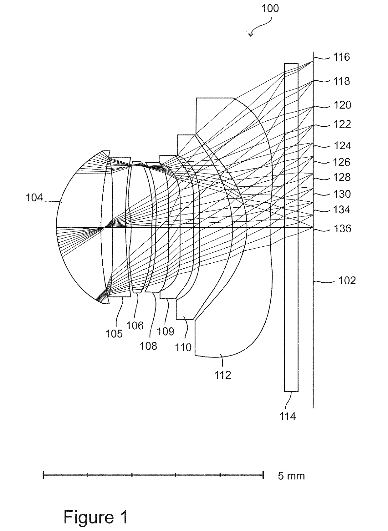
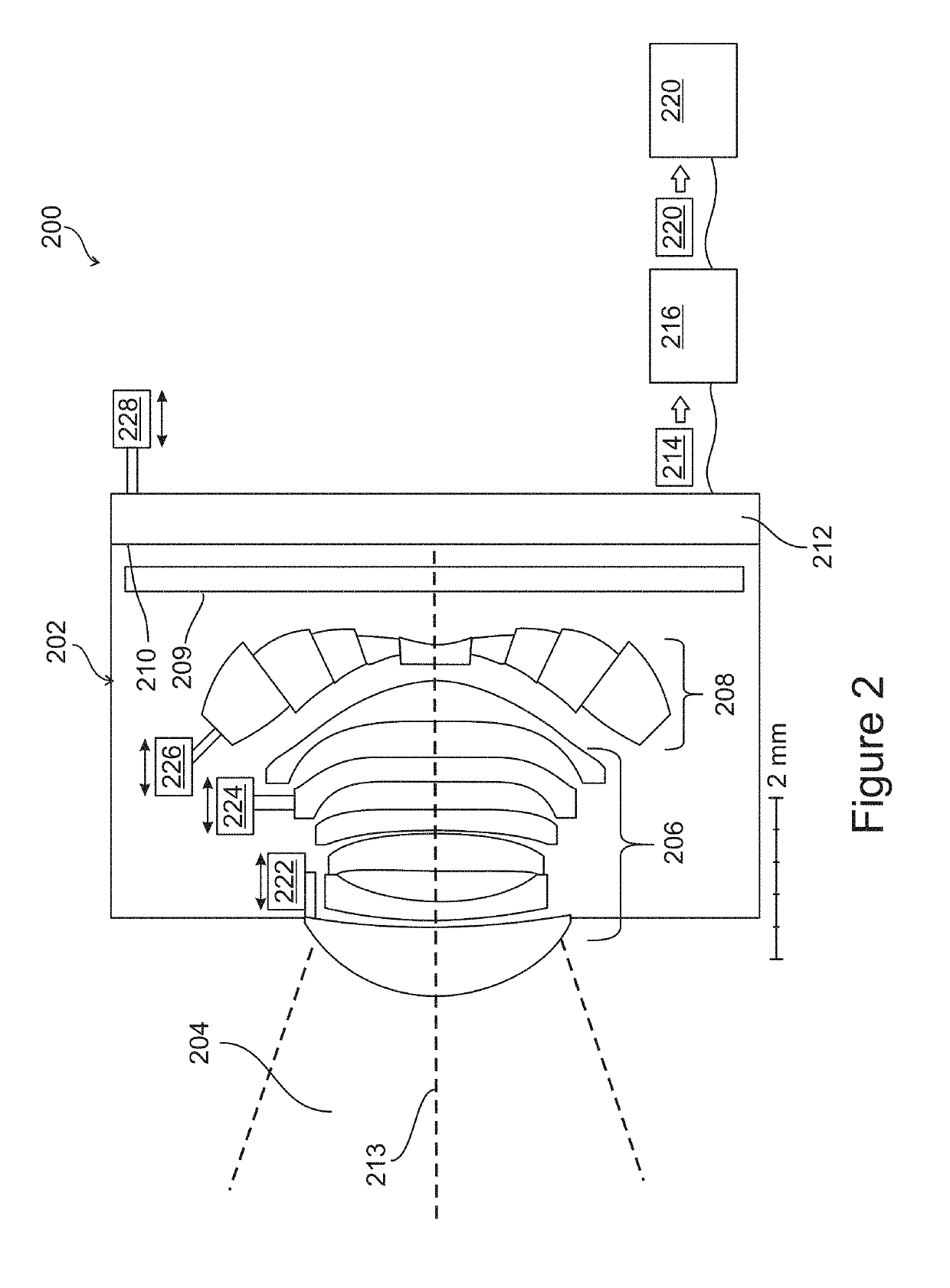
[0192]An analysis was made of the sensitivity of image quality to manufacturing errors, for two designs for cell phone cameras. The first design is a conventional design, similar to that shown in FIG. 1, and the second design has a sectioned lens element, according to an exemplary embodiment of the invention, similar to the design show in FIG. 2, with a central circular section surrounded by four concentric annular sections. Both designs have a total track length (TTL) from the aperture to the sensor of 5.7 mm, both have an f / 1.4 aperture, both have a field of view that is 80 degrees wide, both have an image height of 7.8 mm, and both have a sensor array with sensor elements (pixels) spaced at a distance of 1.55 μm. A calculation was made of the degradation of image quality that would result from manufacturing errors...


PUM


Abstract

An optical system that produces a digital image of a field of view, comprising:a) a sensor array of light sensors that produces an output signal indicating an intensity of light received by each light sensor;b) one or more optical elements that together project an image of the field of view onto the sensor array, including at least one sectioned optical element comprising a plurality of sections, at least two of the sections differing in one or both of size and shape, each section projecting onto the sensor array an image of only a portion of the field of view, the different sections projecting images of different portions of the field of view to non-overlapping regions of the sensor array.

Description

RELATED APPLICATIONS[0001]This application claims the benefit of priority under 35 USC § 119(e) of U.S. Provisional Patent Application No. 62 / 569,650, filed on Oct. 9, 2017, the contents of which are incorporated by reference as if fully set forth herein in their entirety.[0002]This application is also related to co-filed, co-pending and co-assigned Chinese Patent Application entitled “LENS DESIGN WITH TOLERANCE OF FABRICATION ERRORS” (Attorney Docket No. 75432), the disclosure of which is incorporated herein by reference.FIELD AND BACKGROUND OF THE INVENTION[0003]The present invention, in some embodiments thereof, relates to designs of optical systems and, more particularly, but not exclusively, to lens designs for imaging systems and for projection systems, with improved manufacturing tolerances.[0004]Cameras used in cell phones typically have very short distance from the first surface of the lens to the sensor, in order to fit into the thickness of the phone. In order to have hig...

Claims


Application Information

Patent Timeline
Patent Type & Authority Applications(United States)
IPC IPC(8): G02B3/00G06T5/00G06T7/11G06T5/50H04N5/225
CPCG02B3/0037G06T5/002G06T7/11G06T5/50H04N5/2254G06T2207/20212G02B27/0012G06T5/006G06F30/20G02B13/0045G02B13/0055G02B9/64G02B3/06H04N23/55
Inventor SADE, SHARON
Owner IPHYSICIST
Why Eureka
Try Eureka