Bundle branch pacing devices and methods

a pacing device and branch branch technology, applied in the field of pacing using the conduction system of the heart, can solve the problems of significantly delayed heart beat process, inability to maintain synchrony with the right ventricle, and significantly inefficient left ventricle at pumping blood to the body, so as to achieve better ventricular synchronization and better pacing timing and output

Pending Publication Date: 2019-04-18
MEDTRONIC INC
View PDF0 Cites 11 Cited by
  • Summary
  • Abstract
  • Description
  • Claims
  • Application Information

AI Technical Summary

Benefits of technology

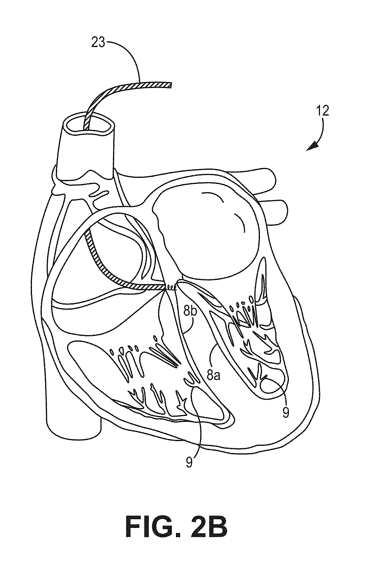
[0007]The techniques of this disclosure generally relate to pacing the special cardiac conductive system, e.g., the His-Purkinje system, including His bundle and bundle branches. A conduction block can either exist due to disease progression, such as AV block or infra-Hisian block, or appear during the lead implantation procedure that causes bundle injury or otherwise affects bundle conduction. In such cases, conventional His bundle pacing may not work properly. For example, activation can propagate via one bundle branch but not the other one. Thus, this disclosure provides bundle branch pacing by bypassing the block region and algorithms that allow better pacing timing and output to provide a better ventricular synchronization than conventional His bundle pacing. For example, if a pacing lead is placed near the left bundle branch and a low pacing output only excites the left bundle branch but not the right bundle branch, an algorithm of the present disclosure will adjust pacing timing to synchronize the activation generated by pacing with intrinsic activation via the right bundle branch, which may result in a normal ventricular synchronization. In another example, if the lead placement damages or otherwise affects the right bundle branch and can only stimulate the left bundle branch, which may lead to an electrocardiogram (ECG) representing a right bundle branch block, or a sign of ventricular dyssynchrony, then a new lead of the present disclosure may be used to stimulate both left and right bundle branches at the same time to achieve synchronized right and left ventricular activation.

Problems solved by technology

However, the heart beat process may be significantly delayed because the pulse travels from the right ventricle through the left ventricle.
Delayed electrical pulses can cause the left ventricle to be unable to maintain synchrony with the right ventricle.
Over time, the left ventricle can become significantly inefficient at pumping blood to the body.
In some patients, heart failure can develop such that the heart is too weak to pump blood to the body.
Heart failure may be a devastating diagnosis since, for example, fifty percent of the heart failure patients have a life expectancy of five years.
Conduction through the AV nodal tissue takes longer than through the atrial tissue, resulting in a delay between atrial contraction and the start of ventricular contraction.
While His bundle pacing is increasingly used as an alternative to traditional pacing techniques, His bundle pacing has not been widely adopted for a variety of reasons.
Further, some physicians insert the pacing electrode in a manner that damages the His bundle thereby causing complete block or bundle branch block timing of delivery of pacing pulses not being optimal.
In such cases, conventional His bundle pacing may not work properly.

Method used


Image

  • Bundle branch pacing devices and methods
  • Bundle branch pacing devices and methods
  • Bundle branch pacing devices and methods

Examples


embodiment a10

[0312 is a method of any A embodiment, wherein the time interval for bundle pacing is adjusted by increasing up to 10 ms or decreasing down to 10 ms.

embodiment a11

[0313 is a method of using an implantable medical device having a processor and an electrical pulse generator comprising: using the processor to control the electrical pulse generator to adjust delivery of bundle pacing. The processor is configured to: measure a QRS parameter and determine whether the QRS parameter is larger than a threshold; in response to determining that the QRS parameter is greater than or equal to the threshold, adjust a bundle-pacing to ventricular-activation interval or a bundle pacing output level; and deliver bundle pacing using the adjusted bundle-pacing to ventricular-activation interval or using the adjusted bundle pacing output level.

embodiment a12

[0314 is an implantable medical device for His-bundle or bundle-branch pacing of a patient's heart comprising: a sensing circuit configured to sense an atrial event (As) and a ventricular event (Vs); an electrical pulse generator configured to generate and deliver electrical His-bundle or bundle-branch stimulation pulses (Vp); a processor coupled to the sensing circuit and the electrical pulse generator and configured to control the electrical pulse generator to deliver said Vp on expiration of a defined AV interval or Vp-Vs interval following a said As or Vs. The processor is further configured to: determine whether Vp timing should be adjusted; in response to determining that the Vp timing should be adjusted, determine whether Vp should be delivered earlier or later; in response to determining whether the Vp should be delivered earlier or later, decrease an AV delay if the Vp should be delivered earlier or increase the AV delay in response to determining Vp should be delivered lat...


PUM


Abstract

The present disclosure relates generally to pacing of cardiac tissue, and more particularly to adjusting delivery of His bundle or bundle branch pacing in a cardiac pacing system to achieve synchronized ventricular activation. A left bundle branch (LBB) cathode electrode may be implanted a left side of the septum of the patient's heart proximate to the LBB, and a right bundle branch (RBB) cathode electrode may be implanted on a right side of the septum of the patient's heart proximate to the RBB. One or both cathode electrodes may be used to deliver synchronized left and right bundle-branch pacing based on one or both of an atrial event and a ventricular event. A device for bundle branch pacing may be implanted based on determining whether an LBB block pattern or an RBB block pattern is present in monitored electrical activity.

Description

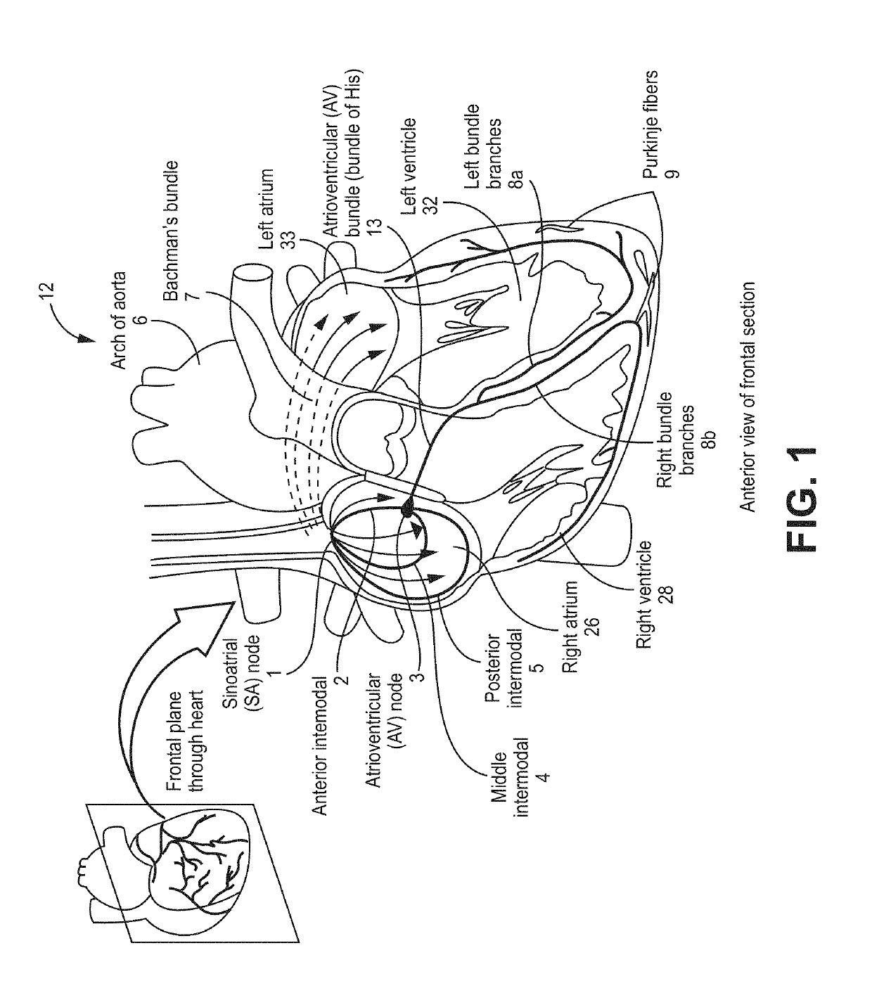
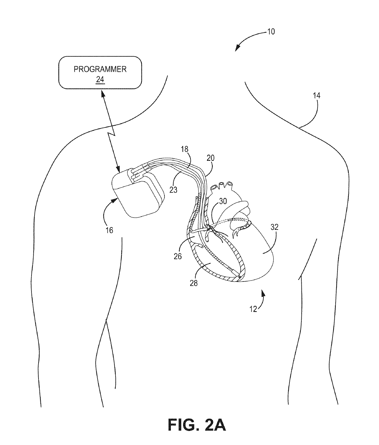
CROSS-REFERENCE TO RELATED APPLICATIONS[0001]This application claims the benefit of U.S. Provisional Application No. 62 / 573,685, filed Oct. 17, 2017, the benefit of U.S. Provisional Application No. 62 / 581,486, filed Nov. 3, 2017, and the benefit of U.S. Provisional Application No. 62 / 617,059, filed Jan. 12, 2018, which are incorporated herein in their entireties.[0002]The present disclosure relates generally to pacing of cardiac tissue, and more particularly, to pacing using the conduction system of the heart, such as the His bundle.[0003]Implantable medical devices (IMDs), such as cardiac pacemakers or implantable cardioverter defibrillators, deliver therapeutic stimulation to patients' hearts thereby improving the lives of millions of patients living with heart conditions. Conventional pacing techniques involve pacing one or more of the four chambers of patient's heart 12—left atrium (LA) 33, right atrium (RA) 26, left ventricle (LV) 32 and right ventricle (RV) 28, all of which ar...

Claims


Application Information

Patent Timeline
Patent Type & Authority Applications(United States)
IPC IPC(8): A61N1/368
CPCA61N1/3684A61N1/3682A61N1/3686A61N1/3627A61B5/0472A61B5/0464A61N1/056A61N1/3688A61N1/3756A61N1/37282A61N1/36507A61N1/36585A61N1/37211A61B5/686A61B5/7282A61B5/366A61N1/3956A61N1/37264A61N1/37288A61B5/6869A61B5/283A61B5/349A61B5/24A61B5/363A61B5/7235A61N1/3704
Inventor ZHOU, XIAOHONG
Owner MEDTRONIC INC
Why Eureka
Try Eureka