
Cylinder block

a technology of cylinder block and cylinder head, which is applied in the direction of liquid cooling, cylinders, sealing arrangements of engines, etc., can solve the problems of affecting the performance of the engine, so as to improve the thermal insulation performance of the lower portion, improve the thermal insulation performance of the upper portion, and prevent overheating the upper portion. , the effect of increasing the flow velocity of coolan

Active Publication Date: 2019-04-18
HYUNDAI MOTOR CO LTD +1
View PDF2 Cites 0 Cited by
  • Summary
  • Abstract
  • Description
  • Claims
  • Application Information

AI Technical Summary

Benefits of technology

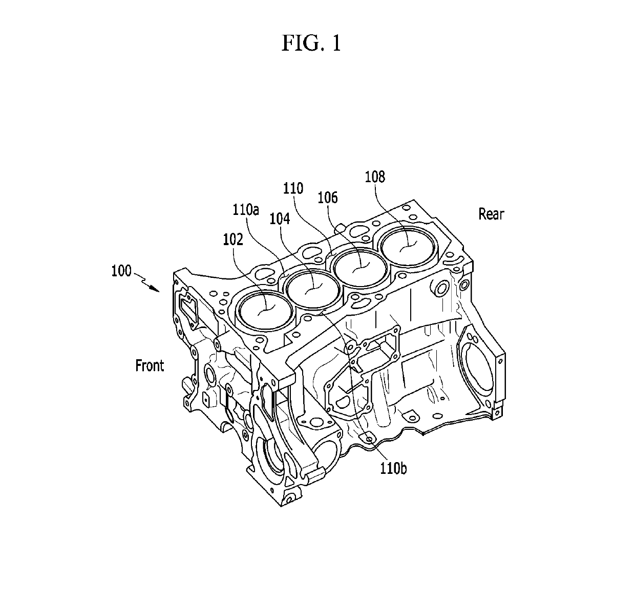
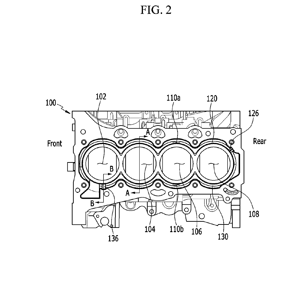
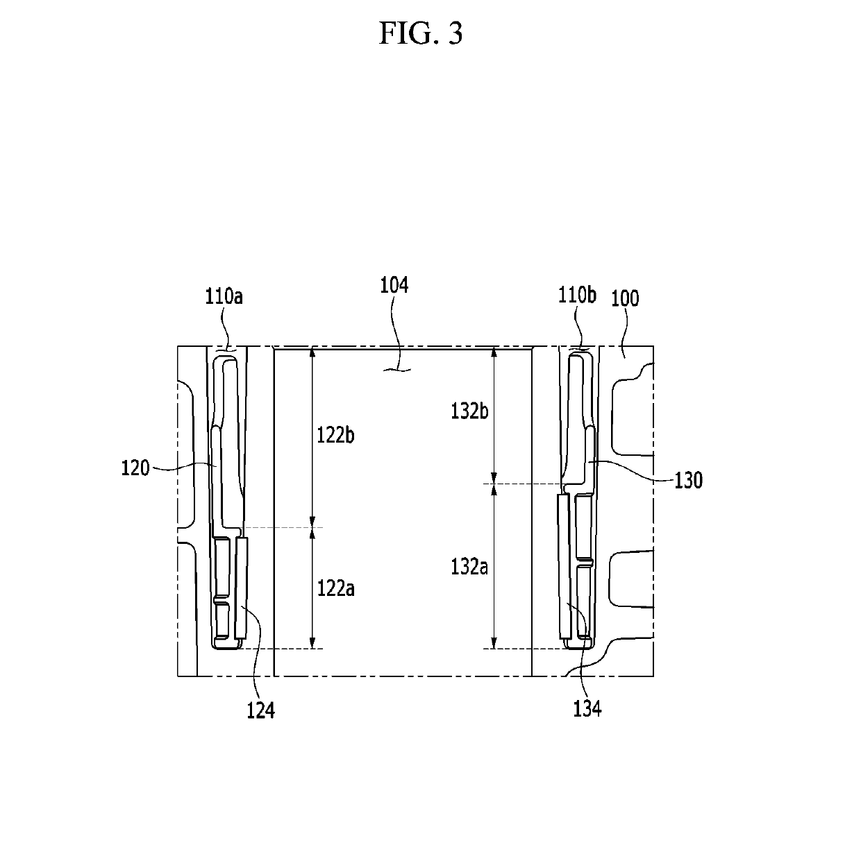
The patent text describes a cylinder block that is designed to have separate cooling for the upper and lower parts of the block. This helps to minimize the temperature differences between the cylinders.

Problems solved by technology

If temperatures of these components are excessively increased, the components are thermally deformed or a defect in lubrication occurs due to damage to an oil film on an inner wall of a cylinder, and thus a thermal problem occurs.
The thermal problem of the engine causes abnormal combustion such as a combustion defect and knocking, which causes serious damage such as melting of the piston.
In addition, there is a problem in that thermal efficiency and engine output may deteriorate.
On the contrary, because excessive cooling of the engine causes problems of deterioration in engine output and fuel economy and low-temperature abrasion of the cylinder, it is necessary to appropriately control a temperature of the coolant.
However, in the engine in the related art, the coolant, which is introduced in order of the cylinders, circulates in the water jacket applied to the cylinder block, and as a result, there is a problem in that cylinder blocks corresponding to upper and lower portions of the combustion chamber where there occurs a relative temperature difference cannot be effectively cooled, such that an overall effect of cooling the engine is inadequate.
In particular, the upper portion of the cylinder block, which is close to the combustion chamber, may become overheated, which causes various problems.
Meanwhile, the lower portion of the cylinder block, which is comparatively distant from the combustion chamber, may be excessively cooled, which causes an increase in time required for warming-up.

Method used


Image

  • Cylinder block
  • Cylinder block
  • Cylinder block

Examples


Embodiment Construction

[0031]It is understood that the term “vehicle” or “vehicular” or other similar term as used herein is inclusive of motor vehicles in general such as passenger automobiles including sports utility vehicles (SUV), buses, trucks, various commercial vehicles, watercraft including a variety of boats and ships, aircraft, and the like, and includes hybrid vehicles, electric vehicles, plug-in hybrid electric vehicles, hydrogen-powered vehicles and other alternative fuel vehicles (e.g. fuels derived from resources other than petroleum). As referred to herein, a hybrid vehicle is a vehicle that has two or more sources of power, for example both gasoline-powered and electric-powered vehicles.

[0032]The terminology used herein is for the purpose of describing particular embodiments only and is not intended to be limiting of the disclosure. As used herein, the singular forms “a,”“an” and “the” are intended to include the plural forms as well, unless the context clearly indicates otherwise. It wil...


PUM


Abstract

A cylinder block includes: a plurality of cylinders; a water jacket through which a coolant flows along an outer periphery of the plurality of cylinders; and insertion members which are inserted into the water jacket formed at both sides of the plurality of cylinders in order to separately cool upper and lower portions of the plurality of cylinders, in which the insertion members restrict a flow of the coolant at a lower side of the water jacket and generate a flow of the coolant at an upper side of the water jacket.

Description

CROSS-REFERENCE TO RELATED APPLICATION[0001]This application claims under 35 U.S.C. § 119(a) the benefit of Korean Patent Application No. 10-2017-0134048 filed in the Korean Intellectual Property Office on Oct. 16, 2017, the entire contents of which are incorporated herein by reference.BACKGROUND(a) Technical Field[0002]The present disclosure relates to a cylinder block of a vehicle engine, more particularly to a cylinder block capable of implementing a cross flow type coolant flow by having an insertion member in a water jacket.(b) Description of the Related Art[0003]In general, heat generated in a combustion chamber of an engine is partially absorbed by a cylinder head, a cylinder block, intake and exhaust valves, a piston, and the like. If temperatures of these components are excessively increased, the components are thermally deformed or a defect in lubrication occurs due to damage to an oil film on an inner wall of a cylinder, and thus a thermal problem occurs.[0004]The thermal...

Claims


Application Information

Patent Timeline
Patent Type & Authority Applications(United States)
IPC IPC(8): F02F1/14F01P3/02
CPCF02F1/14F01P3/02F01P2003/021F02F11/005
Inventor LEE, BYUNG SOOLEE, BONG SANG
Owner HYUNDAI MOTOR CO LTD
Learn More