Imaging optical lens, imaging apparatus and electronic device

a technology of applied in the field of imaging optical lenses and imaging apparatus, can solve the problems of difficult to obtain size, difficult to achieve image quality balance, and difficulty in achieving view angles, apertures, and size requirements

Active Publication Date: 2019-04-18
LARGAN PRECISION
View PDF0 Cites 11 Cited by
  • Summary
  • Abstract
  • Description
  • Claims
  • Application Information

AI Technical Summary

Benefits of technology

[0012]wherein a central thickness of the second lens element is CT2, an axial distance between the first lens element and the second lens element is T12, a focal length of the imaging optical lens is f, a curvature radius of an object-side surface of the fourth lens element is R7, a curvature radius of an image-side surface of the fourth lens element is R8, a curvature radius of an image-side surface of the fifth lens element is R10, a focal length of the first lens element is f1, a focal length of the sixth lens element is f6, and the following conditions are satisfied:

Problems solved by technology

Also, with growing popularities of portable devices, requirements to the size of the shooting lenses are becoming even harsher.
Due to shapes and interspacing of lens elements of conventional shooting lenses not being properly arranged, balances among image qualities, view angles, apertures, and sizes cannot be easily obtained.

Method used


Image

  • Imaging optical lens, imaging apparatus and electronic device
  • Imaging optical lens, imaging apparatus and electronic device
  • Imaging optical lens, imaging apparatus and electronic device

Examples


1st embodiment

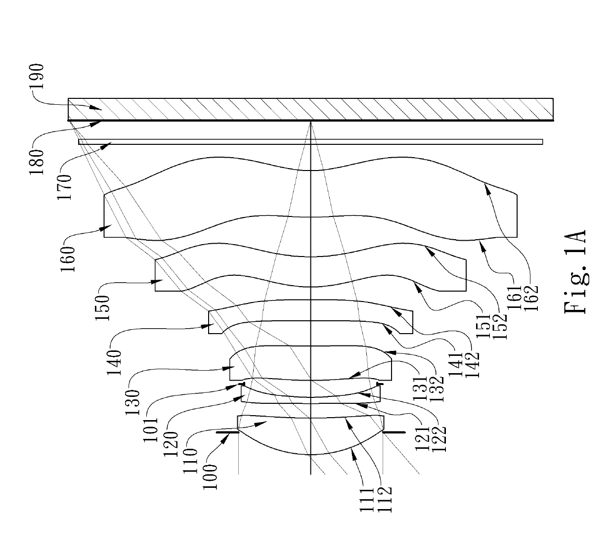
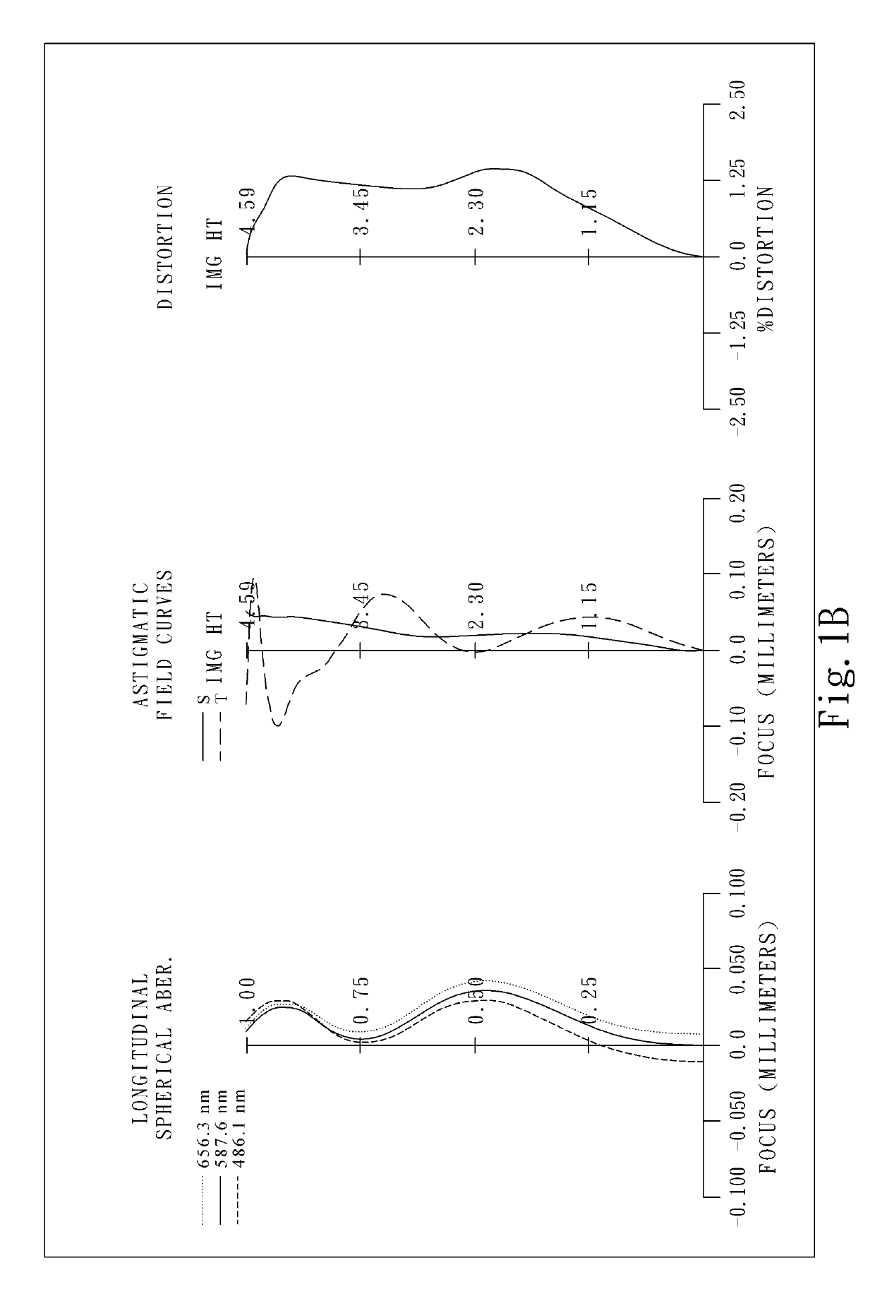
[0072]FIG. 1A is a schematic view of an imaging apparatus according to the 1st embodiment of the present disclosure. FIG. 1B shows, in order from left to right, longitudinal spherical aberration curves, astigmatic field curves and a distortion curve of the imaging apparatus according to the 1st embodiment.

[0073]In FIG. 1A, the imaging apparatus includes an imaging optical lens (not otherwise herein labeled) of the present disclosure and an image sensor 190. The imaging optical lens includes six lens elements, the six lens elements being, in order from an object side to an image side, a first lens element 110, a second lens element 120, a third lens element 130, a fourth lens element 140, a fifth lens element 150, and a sixth lens element 160 and no other lens elements are inserted between the first lens element 110 and the sixth lens element 160.

[0074]The first lens element 110 with positive refractive power has an object-side surface 111 being convex in a paraxial region thereof, a...

2nd embodiment

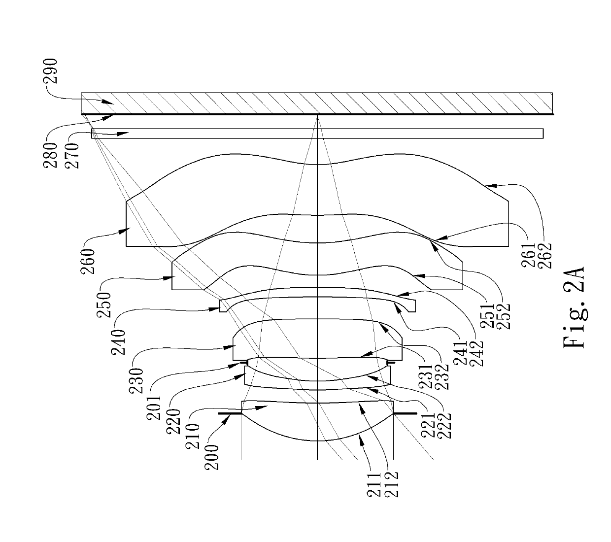
[0114]FIG. 2A is a schematic view of an imaging apparatus according to the 2nd embodiment of the present disclosure. FIG. 2B shows, in order from left to right, longitudinal spherical aberration curves, astigmatic field curves and a distortion curve of the imaging apparatus according to the 2nd embodiment.

[0115]In FIG. 2A, the imaging apparatus includes an imaging optical lens (not otherwise herein labeled) of the present disclosure and an image sensor 290. The imaging optical lens includes six lens elements, the six lens elements being, in order from an object side to an image side, a first lens element 210, a second lens element 220, a third lens element 230, a fourth lens element 240, a fifth lens element 250, and a sixth lens element 260 and no other lens elements are inserted between the first lens element 210 and the sixth lens element 260.

[0116]The first lens element 210 with positive refractive power has an object-side surface 211 being convex in a paraxial region thereof, a...

3rd embodiment

[0127]FIG. 3A is a schematic view of an imaging apparatus according to the 3rd embodiment of the present disclosure. FIG. 3B shows, in order from left to right, longitudinal spherical aberration curves, astigmatic field curves and a distortion curve of the imaging apparatus according to the 3rd embodiment.

[0128]In FIG. 3A, the imaging apparatus includes an imaging optical lens (not otherwise herein labeled) of the present disclosure and an image sensor 390. The imaging optical lens includes six lens elements, the six lens elements being, in order from an object side to an image side, a first lens element 310, a second lens element 320, a third lens element 330, a fourth lens element 340, a fifth lens element 350, and a sixth lens element 360 and no other lens elements are inserted between the first lens element 310 and the sixth lens element 360.

[0129]The first lens element 310 with positive refractive power has an object-side surface 311 being convex in a paraxial region thereof, a...


PUM


Abstract

An imaging optical lens includes six lens elements, the six lens elements being, in order from an object side to an image side: a first lens element; a second lens element having an image-side surface being concave in a paraxial region thereof, a third lens element having an object-side surface being convex in a paraxial region thereof, a fourth lens element, a fifth lens element, and a sixth lens element having negative refractive power.

Description

RELATED APPLICATIONS[0001]This application claims priority to Taiwan Application Serial Number 106135318, filed on Oct. 16, 2017, which is incorporated by reference herein in its entirety.BACKGROUNDTechnical Field[0002]The present disclosure relates to an imaging optical lens and an imaging apparatus, and more particularly, to an imaging optical lens and an imaging apparatus applicable to electronic devices.Description of Related Art[0003]With rapid developments in technology, shooting lenses are even wildly utilized in various fields such that demands to the shooting lenses with wide angle of view and high image quality are increasing. Meanwhile, for scenes such as dynamic photography and night shooting, shooting lenses with large aperture are indispensible. Also, with growing popularities of portable devices, requirements to the size of the shooting lenses are becoming even harsher.[0004]Due to shapes and interspacing of lens elements of conventional shooting lenses not being prop...

Claims


Application Information

Patent Timeline
Patent Type & Authority Applications(United States)
IPC IPC(8): G02B13/00G02B27/00
CPCG02B13/0045G02B27/0025G02B13/06G02B9/62
Inventor HSUEH, CHUN-CHEKUO, TZU-CHIEH
Owner LARGAN PRECISION
Why Eureka
Try Eureka