Supercharge Your Innovation With Domain-Expert AI Agents!

Blade ring segment for turbine section, turbine section having the same, and gas turbine having the turbine section

a turbine section and turbine section technology, applied in the field of blades, can solve problems such as damage to the blade ring segment, and achieve the effect of improving cooling efficiency and improving cooling efficiency

Active Publication Date: 2019-04-25
DOOSAN HEAVY IND & CONSTR CO LTD
View PDF8 Cites 1 Cited by
  • Summary
  • Abstract
  • Description
  • Claims
  • Application Information

AI Technical Summary

Benefits of technology

The present patent text aims to provide a blade ring segment for a turbine, a turbine section with the blade ring segment, and a gas turbine with the turbine section, which improve cooling efficiency to prevent damage caused by high thermal loads. The blade ring segment has modified cooling channels through which external cooling air flows, and multiple protruding blocks with flowing holes have been added to improve cooling efficiency. Overall, the patent text introduces a new cooling structure for the blade ring segment to achieve improved cooling efficiency and prevent damage caused by high thermal loads.

Problems solved by technology

Here, in each of blade ring segments, one side facing the internal space of the casing is exposed to the high temperature and high-pressure combustion gas and subjected to high thermal load, which may damage the blade ring segment.

Method used


Image

  • Blade ring segment for turbine section, turbine section having the same, and gas turbine having the turbine section
  • Blade ring segment for turbine section, turbine section having the same, and gas turbine having the turbine section
  • Blade ring segment for turbine section, turbine section having the same, and gas turbine having the turbine section

Examples


first embodiment

[0060]FIG. 5 is a plan view of a modified example of the outer panel according to the Referring to FIG. 5, the rectangular parallelepiped blocks 1461 are arranged such that the longitudinal direction thereof is perpendicular to an axis of the turbine casing part. When flowing from the upstream to the downstream of the turbine, the cooling air fed through the air holes flows along the first flowing channel 1450 having a zigzag pattern.

second embodiment

[0061]FIG. 6 is an exploded perspective view of a blade ring segment for a turbine section according to the present disclosure, and FIG. 7 is a plan view of an outer panel of the blade ring segment shown in FIG. 6.

[0062]Referring to FIGS. 6 and 7, the blade ring segment 2400 according to the second embodiment includes an inner panel 2420, an outer panel 2440, and a cooling structure 2460.

[0063]The blade ring segment is different from that of the first embodiment in that the cooling structure is modified.

[0064]The same components of the blade ring segment as that of the first embodiment will not be described, but the cooling structure 2460 different from that of the first embodiment will be described.

[0065]The cooling structure 2460 has rows of protruding blocks 2461 each having a hexagonal prism shape. Rows of protruding blocks 2461 are alternately provided in a staggered arrangement with each other, thereby forming a first flowing channel having a zigzag pattern.

[0066]The protrudin...

third embodiment

[0070]FIG. 8 is a plan view of an outer panel of a blade ring segment for a turbine section according to the present disclosure.

[0071]Referring to FIG. 8, the blade ring segment 3400 according to the third embodiment includes an inner panel, an outer panel, and a cooling structure.

[0072]The blade ring segment is different from that of the first embodiment in that the cooling structure is modified.

[0073]The same components of the blade ring segment as that of the first embodiment will not be described, but the cooling structure different from that of the first embodiment will be described.

[0074]The cooling structure 3460 has a plurality of angled pieces 3461. The angled pieces are arranged such that adjacent rows of angled pieces 3461 are alternately provided in a staggered arrangement with each other, thereby forming a first flowing channel 3450 having a zigzag pattern.

[0075]The angled piece 3461 each have a ‘A’-type sectional shape, and adjacent angled pieces are alternately dispos...


PUM


Abstract

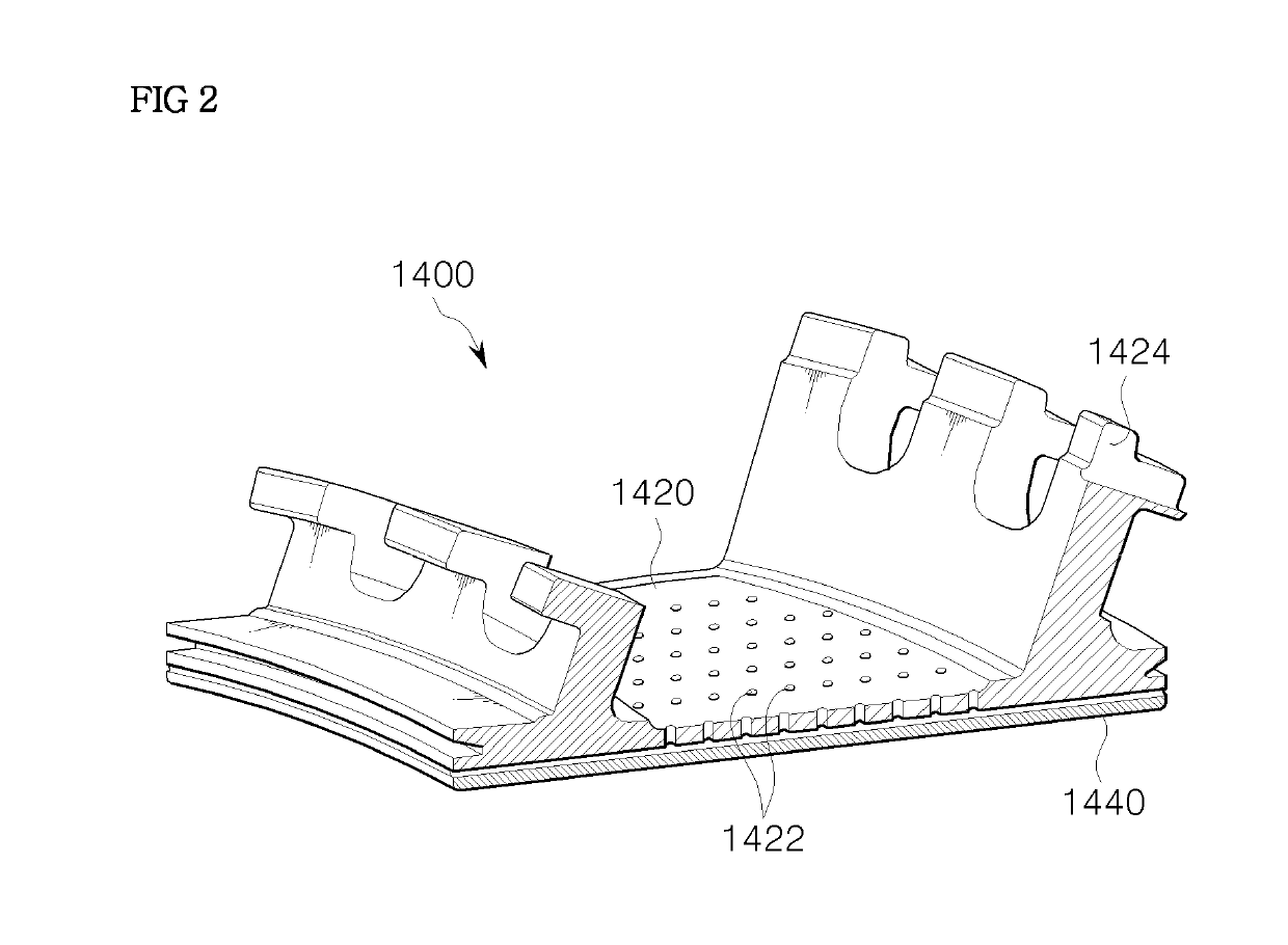
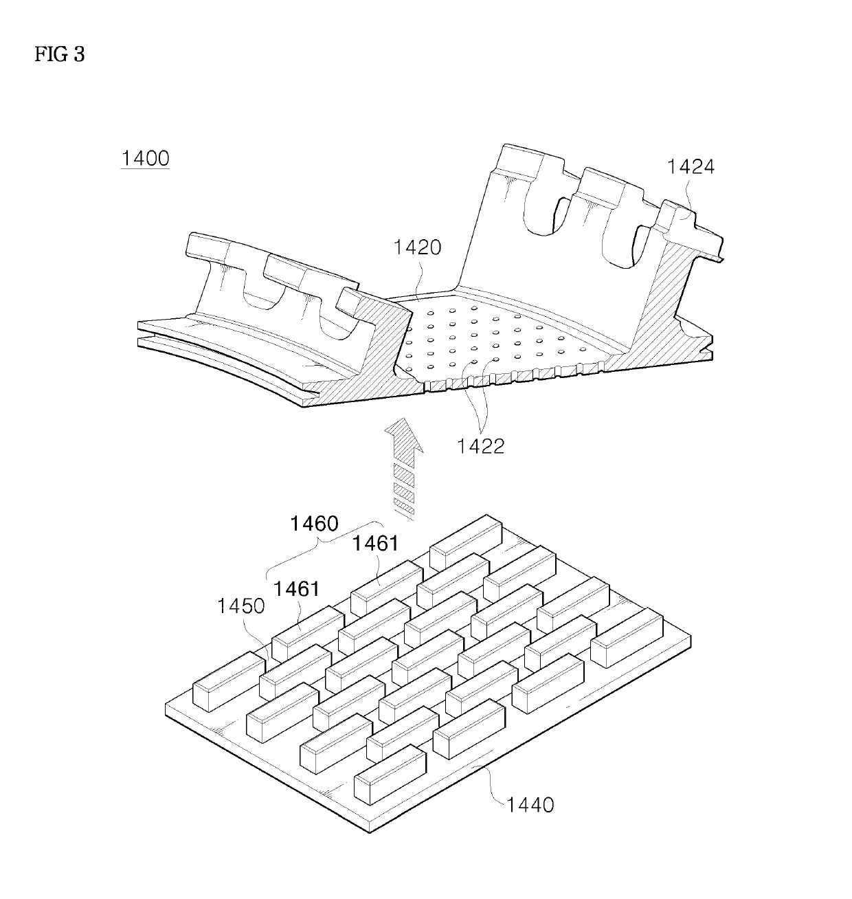
Disclosed are a blade ring segment for a turbine section, a turbine section having the blade ring segment, and a gas turbine having the turbine section. Multiple blade ring segments is installed in a turbine casing accommodating turbine blades rotated by combustion gas from a combustor. The blade ring segment includes an inner panel provided in the turbine casing and having multiple air holes through which cooling air fed from the outside of the turbine casing flows, an outer panel disposed on one side of the inner panel, and a cooling structure protruding from one side of the outer panel so as to form a flowing channel in a zigzag pattern so that cooling air fed through the air holes flows therethrough.

Description

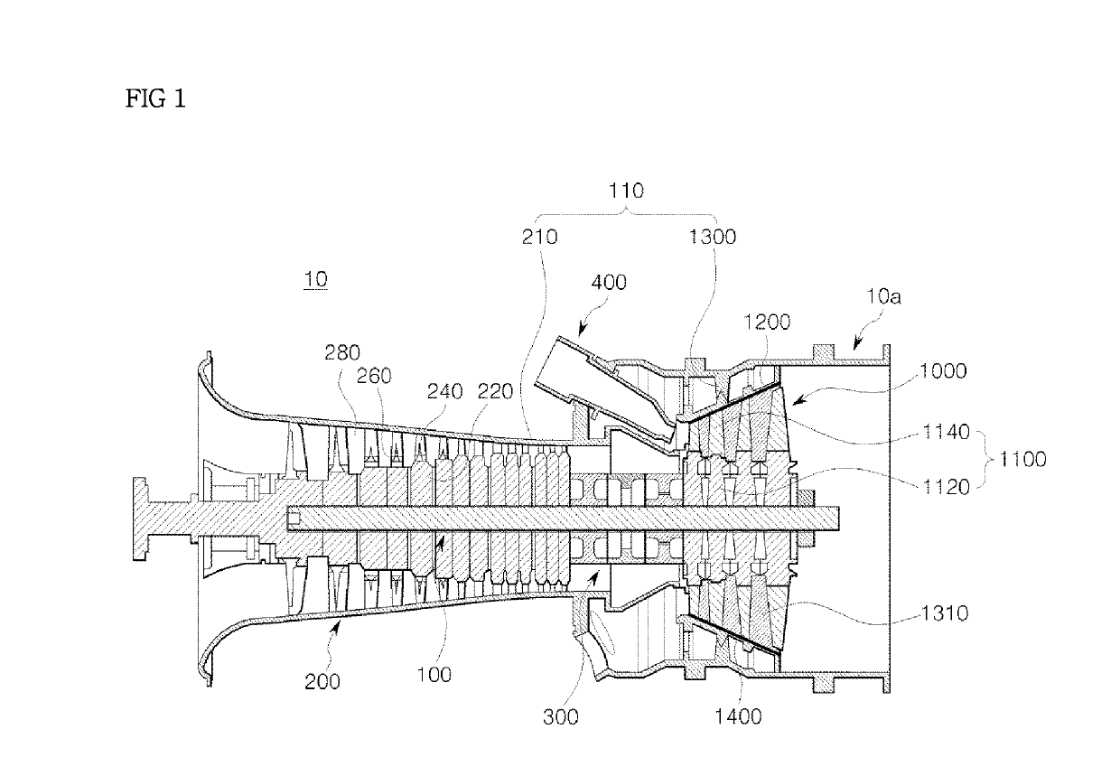
CROSS REFERENCE TO RELATED APPLICATION[0001]The present application claims priority to Korean Patent Application No. 10-2017-0136189, filed on Oct. 20, 2017, the disclosure of which is incorporated herein by reference in its entirety.BACKGROUND OF THE DISCLOSURE1. Field of the Disclosure[0002]The present disclosure relates to a blade ring segment for a turbine which is attached to a turbine casing to prevent leakage of combustion gas and, more particularly, to a blade ring segment for a turbine having an improved cooling structure. The present disclosure also relates to a turbine section having the blade ring segment, and a gas turbine having the turbine section.2. Description of the Background Art[0003]Generally, turbines, such as steam turbines, gas turbines or the like, are machines that obtain rotating force with impulsive force using a flow of compressed fluid, such as gas.[0004]The gas turbine generally includes a compressor, a combustor, and a turbine. The compressor has a co...

Claims


Application Information

Patent Timeline
IPC IPC(8): F01D25/12F01D9/04F01D11/08
CPCF01D25/12F01D9/04F01D11/08F05D2220/32F05D2240/10F05D2260/202F05D2240/11F05D2250/132F05D2250/183F05D2250/221F05D2250/23F05D2250/75F05D2260/201F05D2260/22141F01D9/041F02C7/18F05D2240/81
Inventor KIM, INKYOM
Owner DOOSAN HEAVY IND & CONSTR CO LTD
Features
  • R&D
  • Intellectual Property
  • Life Sciences
  • Materials
  • Tech Scout
  • Unparalleled Data Quality
  • Higher Quality Content
  • 60% Fewer Hallucinations
Learn More