Method and Device for Detecting a Fault of a Barometric Pressure Measuring System Arranged Aboard a Flying Device

Active Publication Date: 2019-04-25
DEUTSCHES ZENTRUM FUER LUFT & RAUMFAHRT EV
View PDF5 Cites 1 Cited by
  • Summary
  • Abstract
  • Description
  • Claims
  • Application Information

AI Technical Summary

Benefits of technology

The invention provides a method and device for easily identifying faults of a pressure measuring system on a flying device, including during a flight. The method uses weather prediction data to improve accuracy and performs automatic self-calibration of the pressure measuring system based on altitude deviation and pressure deviation. This allows for continuous monitoring of the quality of the pressure measuring system in flight operations and can help prevent unsafe flight operations or reduce downtime of the flying device. The method is cost-effective, easy to use, and can be applied to flying devices of all kinds and fields of application.

Problems solved by technology

Measuring errors due to the disturbances mentioned above and the accuracy of the barometric altitude zAC(t) determined would be unacceptable if it were not for the calibration of the pressure measuring system.
Today, determining the required pressure correction in the pressure measuring system requires complex flight tests of the flying device to be tested, measurements on the ground, accompanying measurements during the flight, or the availability of additional experimental equipment on the flying device.
This means that the HMU method requires the use of at least one HMU ground unit, special calibrating flights, partially with additional equipment, and incurs respective additional costs.
Faults of static pressure measurement thus immediately affect faults when determining the dynamic pressure.
The methods for fault detection in barometric pressure measuring systems known in prior art have the disadvantage that they typically require flight tests and are costly and time consuming They particularly make minor changes on the flying device, such as temporary add-ons to / removals from the flying device expensive, time consuming and difficult, because these change the aerodynamics of the flying device and therefore require recalibration of the pressure measuring system.
It is another disadvantage of prior art that neither the pilots nor air traffic controllers have a simple way of monitoring the functioning and precision of the barometric pressure pAC(t) and barometric altitude zAC(t) determined by the pressure measuring system and to determine respective accuracy trends.
Testing the components of the pressure measuring system on the ground cannot sufficiently ensure the precision of the pressure measuring system in flight.
Leakages of the pressure line system will generate measuring errors.
Such faults can for example be caused by incorrect calibration of the pressure measuring system, a defective sensor within the pressure measuring system, leakages / leaks of the pressure measuring system, or faulty electronics of the pressure measuring system.
For example, air traffic control can be informed that the altitude readings of the flying device are unreliable, such that respective action can be taken.
This is particularly true of flying devices having extreme fields of application (altitudes and speeds), in which respective test flights are difficult due to lack of an observer on board or other ways of comparison.

Method used


Image

  • Method and Device for Detecting a Fault of a Barometric Pressure Measuring System Arranged Aboard a Flying Device

Examples


Embodiment Construction

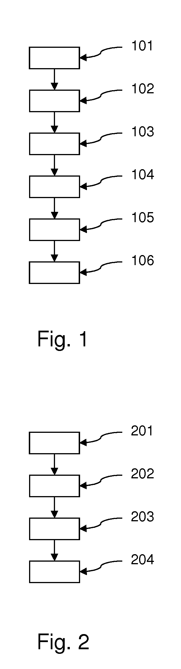
[0069]FIG. 1 shows a schematic flowchart of a variant of the proposed method for determining a fault of a barometric pressure measuring system arranged aboard a flying device. The method includes the following steps.

[0070]In a first step 101, a current position POSGNSS(t) and altitude zGNSS(t) of the flying device in a geodetic reference system at a point in time t is determined using a satellite navigation system GNSS arranged aboard a flying device.

[0071]In a second step 102, a static pressure pAC(t) and / or a pressure level zAC(t) is determined using the pressure measuring system.

[0072]In a third step 103, a geopotential altitude zAN / PROG(t) assigned to the static pressure pAC(t) is determined for the position POSGNSS(t) in provided weather analysis data ANDAT or in provided weather prognosis data PROGDAT of a numerical weather prediction model (NWP), or a static pressure pAN / PROG(t) assigned to the altitude zGNSS(t) is determined for the position POSGNSS(t) in provided weather an...


PUM


Abstract

The invention relates to a method and device for determining a fault of a barometric pressure measuring system arranged aboard a flying device. The method comprises the following steps: determining a current position POSGNSS(t) and an altitude zGNSS(t) of the flying device in a geodetic reference system at a point in time t using a satellite navigation system GNSS arranged aboard a flying device; determining a static pressure pAC(t) and / or a pressure level zAC(t) for the position POSGNSS(t) in provided weather analysis data ANDAT or in provided weather prognosis data PROGDAT of a numerical weather prediction model (NWP) using the pressure measuring system; determining a geopotential altitude ZAN / PROG(t) assigned to the static pressure pAC(t) for the position POSGNSS(t) in provided weather analysis data ANDAT or in provided weather prognosis data PROGDAT of a numerical weather prediction model (NWP); determining a static pressure pAN / PROG(t) assigned to the altitude zGNSS(t); determining the altitude deviation Δz(t)=zGNSS(t)−zAN / PROG(t) and / or determining the pressure deviation Δp(t)=pAC(t)−pAN / PROG(t); determining an altitude deviation Δz* averaged over a period of time Δt from Δz(t)=zGNSS(t)−zAN / PROG(t) and / or a pressure deviation Δp* averaged over a period of time Δt from Δp(t)=pAC(t)−pAN / PROG(t), wherein a fault of the pressure measuring system is deemed detected if the determined averaged altitude deviation |Δz*| is greater than or equal to a specified threshold G1, or if the averaged pressure deviation |Δp*| is greater than or equal to a specified threshold G2; and generating a warning signal if a fault is detected.

Description

CROSS-REFERENCE TO RELATED APPLICATIONS[0001]This application is the U.S. National Phase of International Patent Application No. PCT / EP2017 / 053300, filed on 14 Feb. 2017, which claims benefit of German Patent Application No. 102016106221.9, filed on 5 Apr. 2016, the contents of which are incorporated herein by reference in their entirety.BACKGROUNDField[0002]The invention relates to a method and device for determining a fault of a barometric pressure measuring system arranged aboard a flying device.Related Art[0003]The barometric pressure measuring system of a flying device is particularly used to determine the barometric altitude zAC(t) (=pressure level) of the flying device, which is determined based on the static pressure pAC(t) at the flight level of the flying device in the undisturbed atmosphere. For this purpose, the static pressure pAC(t) is determined during the flight. Pressure is taken from a suitable point on the surface of the flying device (the “static pressure tapping...

Claims


Application Information

Patent Timeline
IPC IPC(8): G01S19/15G01C5/06G01S19/42
CPCG01S19/15G01C5/06G01S19/42G01C21/20
Inventor SCHUMANN, ULRICHCHRISTMANN, CARSTENGIEZ, ANDREAS
Owner DEUTSCHES ZENTRUM FUER LUFT & RAUMFAHRT EV
Why Eureka
Try Eureka