Supercharge Your Innovation With Domain-Expert AI Agents!

Soller slit, x-ray diffraction apparatus, and method

a diffraction apparatus and slit technology, applied in the field of x-ray diffraction apparatus, can solve the problems of large time required for measurement, inability to sufficiently narrow the incident x-ray beam size, and inability to complete measurement in a large amount of time. , to achieve the effect of dissipating the shadow of thin plates, high precision and high resolution

Active Publication Date: 2019-04-25
RIGAKU CORP
View PDF6 Cites 3 Cited by
  • Summary
  • Abstract
  • Description
  • Claims
  • Application Information

AI Technical Summary

Benefits of technology

The present invention provides a soller slit that allows for the measurement of X-ray diffraction from a sample with high resolution and in a short measurement time. The soller slit includes multiple thin plates arranged at a position through which X-rays pass. It prevents the diffraction image on the detector from spreading in the in-plane direction and allows for measurement with a short measurement time and a high resolution. An X-ray diffraction apparatus including the soller slit is also provided, as well as a method for measuring diffracted X-rays using the soller slit.

Problems solved by technology

However, such a method involves movement of the detector for pursuing the measurement, which requires a large amount of time to complete measurement over a desired range.
The problem that X-rays of a uniform intensity become non-uniform on the detector due to the soller slit boards is solved by vibration of the vibrating soller slit.
However, it is not possible to sufficiently narrow the incident X-ray beam size when using X-rays available in a laboratory. FIG. 8 illustrates conventional in-plane diffraction spots.

Method used


Image

  • Soller slit, x-ray diffraction apparatus, and method
  • Soller slit, x-ray diffraction apparatus, and method
  • Soller slit, x-ray diffraction apparatus, and method

Examples


Embodiment Construction

[0026]Next, embodiments of the present invention will be described, referring to the accompanying drawings. For simplicity of explanation, identical components are provided with identical reference numerals throughout the drawings, with duplicate description being omitted.

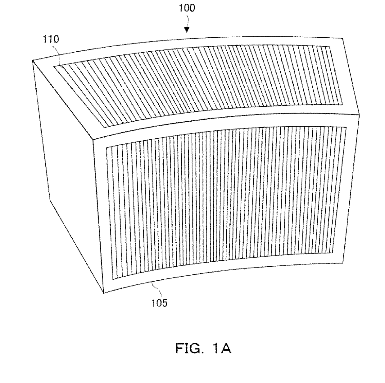
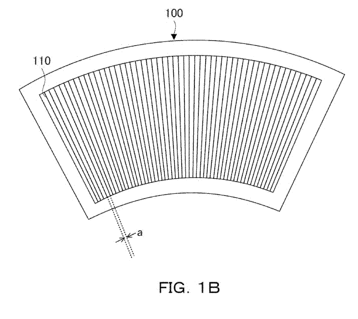
[0027]FIGS. 1A and 1B are a perspective view and a plan view, respectively illustrating a configuration of a soller slit 100. The soller slit 100 is an optical element including a plurality of thin plates 110. The thin plates 110, each being perpendicular to a bottom surface 105, are formed by a metallic X-ray shielding member such as SUS, for example, and arcuately arranged with a predetermined angular interval a between each other of the adjacent plates so as to pass X-rays in a radiating direction from a particular focus. Therefore, when seen from a direction perpendicular to the bottom surface 105, the soller slit 100 is formed in a shape (arcuate) obtained by cutting a small-diameter sector from a large-diamet...


PUM

PropertyMeasurementUnit
thicknessaaaaaaaaaa
angleaaaaaaaaaa
structure analysisaaaaaaaaaa

Abstract

An X-ray diffraction apparatus having a solar slit, and a method for preventing the diffraction image on a detector from spreading in the in-plane direction even when an X-ray irradiation region spreads over the sample surface due to measurement by GIXD, thereby allowing for measurement with a short measurement time and a high resolution. The soller slit 100 includes a plurality of metallic thin plates 110, each being perpendicular to the bottom surface, which are arcuately arranged with a predetermined angular interval between each other so as to pass X-rays in a radiating direction from a particular focus, the soller slit being provided to be used at a position through which X-rays diffracted on a sample surface pass, the particular focus being the center of a goniometer circle, the X-rays being irradiated on a sample at an angle for GIXD.

Description

CROSS-REFERENCE TO RELATED APPLICATION[0001]This application claims priority to Japanese Patent Application No. 2017-206176, filed Oct. 25, 2017, the contents of which are incorporated herein by reference in their entirety.BACKGROUND OF THE INVENTION[0002]The present invention relates to a soller slit including a plurality of thin plates, an X-ray diffraction apparatus and a method using the same.DESCRIPTION OF THE RELATED ART[0003]In recent years, studies on functional organic thin film applied to transistors or solar cells have been drawing attention. In-plane orientation measurement using in-plane diffraction is effective for evaluation of organic thin film. When measuring in-plane diffracted X-rays, structure analysis in the laminating direction is possible, as well as the in-plane direction. For measurement of in-plane diffracted X-rays, there has been conventionally performed a detection method with a zero-dimensional detector using parallel soller slits, as described in Japan...

Claims


Application Information

Patent Timeline
Patent Type & Authority Applications(United States)
IPC IPC(8): G21K1/06G01N23/207G21K1/02G01N23/20016
CPCG21K1/06G01N23/207G21K1/025G01N23/20016
Inventor PINA, LADISLAVINNEMAN, ADOLFOMOTE, KAZUHIKOKOBAYASHI, SHINTARO
Owner RIGAKU CORP
Features
  • R&D
  • Intellectual Property
  • Life Sciences
  • Materials
  • Tech Scout
  • Unparalleled Data Quality
  • Higher Quality Content
  • 60% Fewer Hallucinations
Learn More