
Locking device for pedal vehicles

a technology for locking devices and pedal vehicles, which is applied in the direction of bicycle locks, door/window fittings, wing accessories, etc., can solve the problems of easy tampering, weak structural structure, and difficult installation/deinstallation, so as to simplify the structure of the system/device, improve safety, and improve reliability

Inactive Publication Date: 2019-05-02
PRACCA MARCO +2
View PDF9 Cites 0 Cited by
  • Summary
  • Abstract
  • Description
  • Claims
  • Application Information

AI Technical Summary

Benefits of technology

The patent text discusses the need to make devices safer, simpler, more reliable, and less expensive. Specifically, it focuses on simplifying the structure of locking devices used on pedal vehicles to make them easier to install and use. The technical effects of the patent are the development of a simplified and easier-to-use locking device for pedal vehicles.

Problems solved by technology

The Applicants have in fact noted that the systems of known type are structurally very complex and the complexity thereof makes them structurally weak, easy to tamper with and difficult to install / de-install, if not by qualified personnel, also for reasons related to the different characteristics and dimensions of the central units present on the market.

Method used


Image

  • Locking device for pedal vehicles
  • Locking device for pedal vehicles
  • Locking device for pedal vehicles

Examples


Embodiment Construction

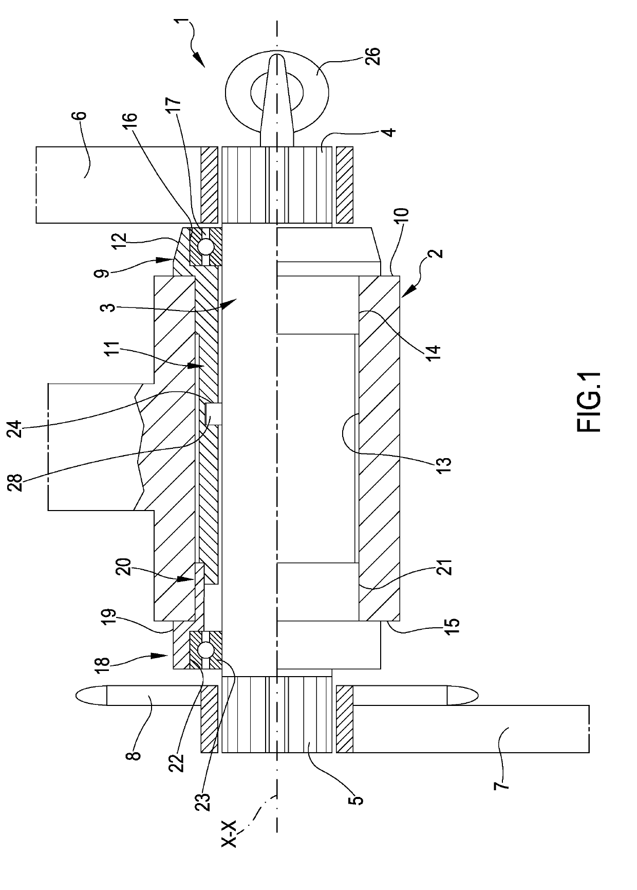
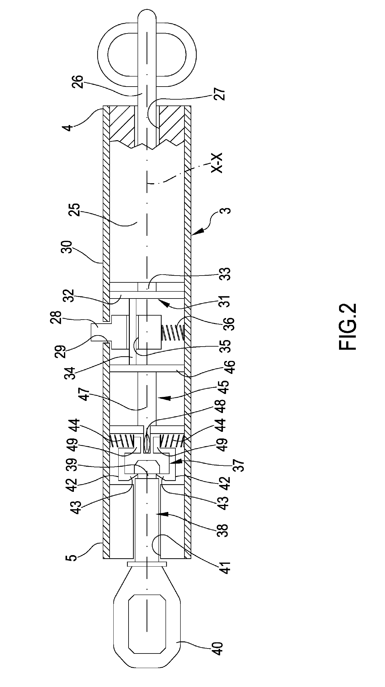
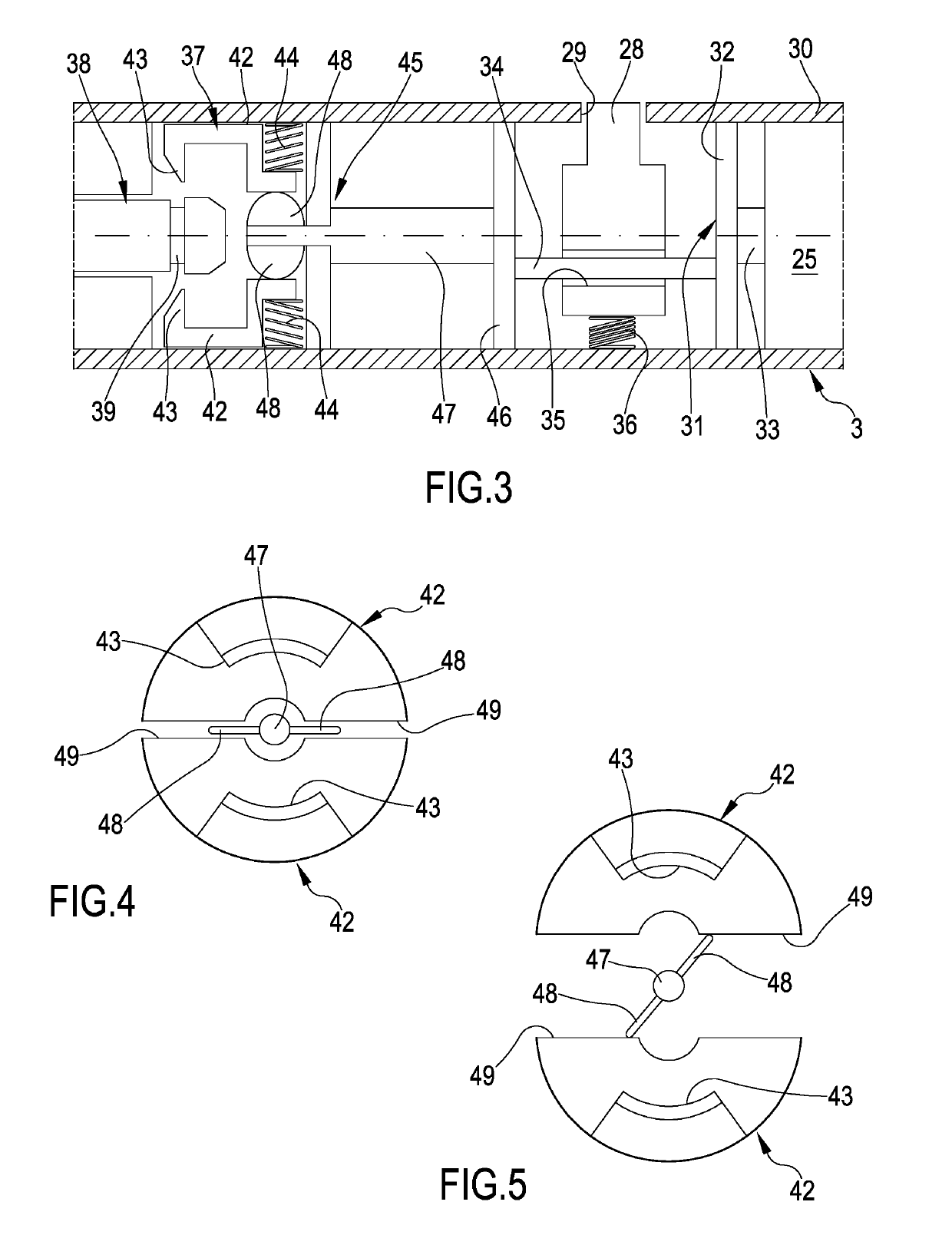
[0060]With reference to the mentioned figures, reference number 1 denotes in its entirety a locking device for pedal vehicles.

[0061]The FIG. 1 illustrates a sleeve 2 of a bicycle. The bicycle is of known type and therefore is not illustrated in its entirety.

[0062]The device 1 is a part of the central movement of the bicycle and comprises a shaft 3 which extends along a rotation axis “X-X” coaxial to the sleeve 2. The shaft 3 also has a first and a second end 4, 5 which are axially opposite one another. The opposite ends 4, 5 each have an external knurling and pedals 67 are mounted on them (the arms but not the cranks are visible) of the bicycle, which rotate solidly with the shaft 3. The second end 5 of the shaft 3 also bears at least a crown wheel 8 of the bicycle.

[0063]The shaft 3 has a cylindrical profile having a circular section with a substantially constant diameter.

[0064]The device 1 comprises a first bushing 9 configured to be mounted and secured to a first axial end 10 of t...


PUM


Abstract

A locking device for pedal vehicles includes: a first bushing; a first bearing mounted in a first housing of the first bushing; a second bushing; a second bearing mounted in a second housing of the second bushing; and a cylindrical body. A shaft is rotatably mounted in the first and second bushing and in the cylindrical body through the first and the second bearing. A lock is operatively connected to the pin to move the pin radially between a radially retracted position, with the pin lying outside of the radial seat, and a radially extracted position, with the pin lying at least partially in the radial seat and preventing rotation of the shaft with respect to the cylindrical body and a sleeve. The shaft integrates a latching mechanism for a safety jack being constrained or constrainable to a safety chain which enables tethering the vehicle, for example, to a pole.

Description

FIELD OF THE INVENTION[0001]The present invention relates to a locking device for pedal vehicles, in particular for bicycles. The present invention relates to the field of mechanical systems adapted to block moving parts of a pedal vehicle so as to prevent and / or dissuade improper use and / or theft thereof. In particular, the present invention relates to a locking device for pedal vehicles configured for selectively blocking the movement of the pedals relative to the sleeve in which the central movement is mounted and therefore relative to the vehicle frame.BACKGROUND OF THE INVENTION[0002]Published document DE19753024 illustrates an anti-theft locking system of bicycles. The system comprises a sleeve arranged internally of the central movement of the bicycle and provided with a radial recess. To block the rotation of the shaft of the bicycle, a security lock is included as well as a security key, by which a pin can slide radially internally of the radial recess. The sleeve is formed...

Claims


Application Information

Patent Timeline
Patent Type & Authority Applications(United States)
IPC IPC(8): B62H5/10B62M3/00B62J99/00
CPCB62H5/10B62M3/003B62J99/00B62J2099/004E05B71/00E05Y2900/50B62J45/00
Inventor MONTELEONE, ALFREDO
Owner PRACCA MARCO
Learn More