Supercharge Your Innovation With Domain-Expert AI Agents!

Aircraft brake cooling fan control system

a technology for controlling systems and air brakes, applied in the direction of aircraft braking arrangements, machines/engines, multi-dynamo-motor starters, etc., can solve problems such as adding mass to aircra

Inactive Publication Date: 2019-05-09
AIRBUS OPERATIONS LTD
View PDF0 Cites 3 Cited by
  • Summary
  • Abstract
  • Description
  • Claims
  • Application Information

AI Technical Summary

Benefits of technology

This solution allows for efficient and mass-reduced brake cooling on aircraft, enabling earlier initiation of cooling and reducing the time required for brake temperature reduction, thereby improving aircraft turnaround times.

Problems solved by technology

A disadvantage of integrated brake cooling fans is that they add mass to the aircraft, which is undesirable.

Method used


Image

  • Aircraft brake cooling fan control system
  • Aircraft brake cooling fan control system
  • Aircraft brake cooling fan control system

Examples


first embodiment

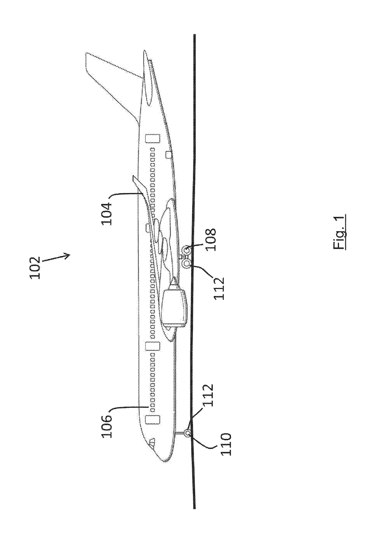
[0051]There now follows a description of specific embodiments, including the first and subsequent illustrated embodiments. FIG. 1 shows, in accordance with a first embodiment, an aircraft 2 on the ground 4. The aircraft has wheels 8 which are in contact with the ground and have associated brakes. In this case, the aircraft has just landed and the aircraft wheel brakes are hot. Before the aircraft takes-off again, the brakes are typically allowed to cool down. This cooling process is accelerated, when the aircraft is on the ground, by using brake cooling fans on the aircraft to cool the brakes by blowing air, from the surrounding environment (e.g. ambient air in the atmosphere), over the brakes and / or their associated structure. As shown schematically in FIG. 2, each fan (represented by box 10) includes an impeller 12 which is driven by an electric motor 14. The motor 14 is in the form of an induction motor powered by three-phase AC electrical power 16 and under the control of a brak...

second embodiment

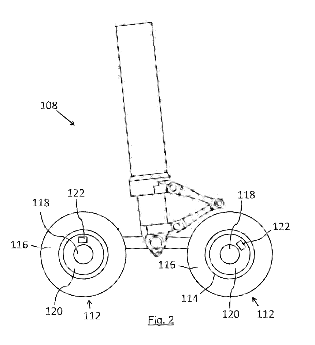
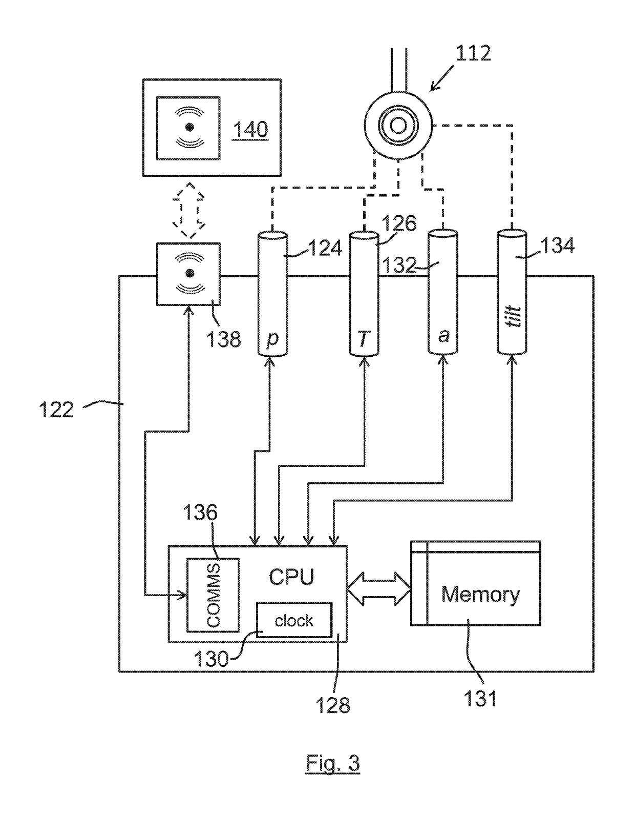
[0054]FIG. 3 shows a landing gear monitoring system 120 according to a In this embodiment, the fans 110 include AC induction motors located within the axles of the braked wheels 108, each driving an impeller housed within a shroud assembly (not shown). The impeller draws air in through the wheel and brake assembly 108, exiting through the debris guard (not shown) mounted on the outer face of the wheel assembly. This cools the brakes quicker than natural conduction and radiation. The control of each brake cooling fan 110 (comprising both motor and impeller) is provided by the landing gear monitoring system 120, which also controls / monitors other aspects of the operation of the landing gear. The landing gear monitoring system 120 controls the brake cooling fans 110 in response to pilot requests issued by means of operating a brake cooling fan switch 130 in the flight-deck. The state of the brake cooling fan switch is indicated by a lamp on the switch 130. A memo on an electronic flig...


PUM


Abstract

An aircraft includes a power source arranged to provide AC electrical power of varying frequency, and a brake cooling fan including an impeller which is driven by an electric motor powered by said AC electrical power for cooling brakes of the aircrafts wheels. The brake cooling fan has an operable mode when the frequency of said AC electrical power meets certain criteria indicating that the frequency of the AC power is suitable for powering the motor, and an inoperable mode to protect against unsuitable operation of the motor. The brake cooling fan may then be safely powered with AC power direct from a wild frequency power network on the aircraft without needing a power inverter or constant power supply generator.

Description

RELATED APPLICATION[0001]This application claims priority to United Kingdom (GB) Patent Application 1509728.0 filed Jun. 4, 2015, and the entirety of which is incorporated by reference.BACKGROUND OF THE INVENTION[0002]The present invention concerns the cooling of brakes on an aircraft by means of brake cooling fans. More particularly, but not exclusively, this invention concerns an aircraft including a brake cooling fan, and a method of cooling an aircraft wheel brake on an aircraft using a brake cooling fan. The invention also concerns an associated control system and an associated computer program product.[0003]The performance of wheel brakes on an aircraft is affected by their temperature. Brake fade is exhibited at high temperatures for example. It is therefore often the case that an aircraft, particularly a commercial passenger aircraft, is prevented, for safety reasons, from taking off if the temperature of the brakes is too high, which if the aircraft has only recently landed...

Claims


Application Information

Patent Timeline
Patent Type & Authority Applications(United States)
IPC IPC(8): F16D65/847F04D25/08H02P1/42F04D27/00H02P1/54H02P29/60
CPCF16D65/847F04D27/008F04D25/08H02P29/60H02P1/42H02P1/54B64C25/42F04D27/00F16D65/78F16D2065/787B64C25/405H02H3/46
Inventor BILL, ANDREW RAYMOND
Owner AIRBUS OPERATIONS LTD
Features
  • R&D
  • Intellectual Property
  • Life Sciences
  • Materials
  • Tech Scout
  • Unparalleled Data Quality
  • Higher Quality Content
  • 60% Fewer Hallucinations
Learn More