Fuse system for at least one load of a vehicle

a technology for fuse systems and vehicles, applied in emergency protection circuit arrangements, emergency protection data processing means, transportation and packaging, etc., can solve problems such as inconvenient disconnection or incorrectness, and achieve the effect of increasing fault toleran

Active Publication Date: 2019-05-09
ROBERT BOSCH GMBH
View PDF0 Cites 6 Cited by
  • Summary
  • Abstract
  • Description
  • Claims
  • Application Information

AI Technical Summary

Benefits of technology

[0005]The fuse system for at least one load of a vehicle according to the invention has the advantage that an evaluation and control unit performs more complex evaluations of the detected load current, preferably using software modules or program code for the at least one load, the execution of which can be completed in the single-digit or multiple-digit microsecond range. In the event of a so-called hard (=low-impedance) short-circuit however, the evaluation and control circuit responds much faster and is even in a position to take decisions on tripping without the involvement of the evaluation and control unit. Embodiments of the fuse system according to the invention can disconnect the load current quickly in the event of a hard short-circuit and still avoid a premature or incorrect disconnection of the load current, where the load current would be switched off even though a sufficient overcurrent is not present. Since in the event of a failure of the evaluation and control unit the originally specified disconnection criteria of the first parameter set can very quickly lead to an incorrect or premature disconnection of the load current, since the evaluation and control unit can no longer take corrective action, the evaluation and control circuit monitors the function of the evaluation and control unit and in case of failure, switches into an emergency operating mode. In emergency mode, the evaluation and control circuit can maintain the function of the fuse protection system in an advantageous way by using an emergency parameter set, even in the event of a failure of the evaluation and control unit. This emergency operation differs significantly from the normal operation, in that all loads, supply lines, etc. can now no longer be optimally protected, but rather the relevant load is protected with, for example, maximum permissible disconnection thresholds. This means that in the emergency mode, embodiments of the fuse system according to the invention do not provide redundant protection functions, but provide fuse protection functions with an increased fault tolerance and a modified protection objective. This allows embodiments to provide a fault-tolerant fuse system, which comprises hardware components and software components.

Problems solved by technology

Since in the event of a failure of the evaluation and control unit the originally specified disconnection criteria of the first parameter set can very quickly lead to an incorrect or premature disconnection of the load current, since the evaluation and control unit can no longer take corrective action, the evaluation and control circuit monitors the function of the evaluation and control unit and in case of failure, switches into an emergency operating mode.

Method used


Image

  • Fuse system for at least one load of a vehicle

Examples


Embodiment Construction

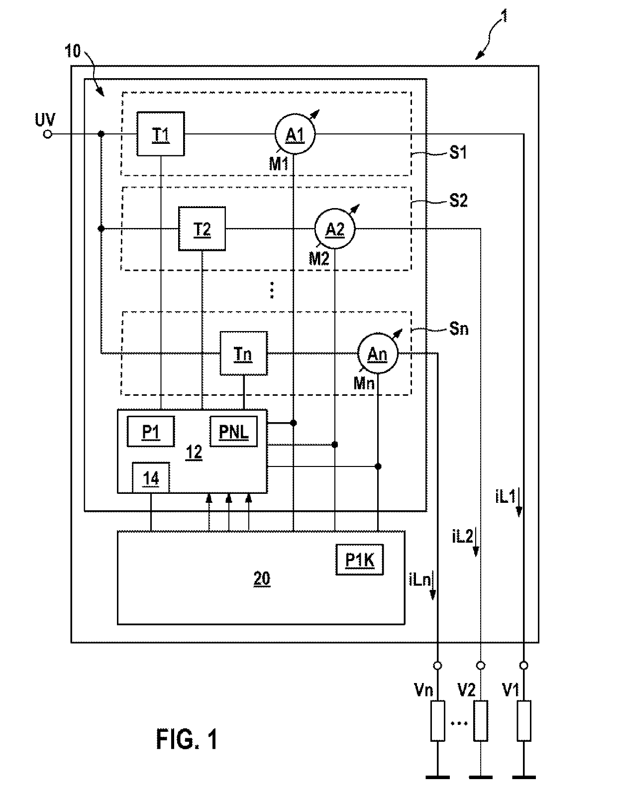
[0017]As is apparent from FIG. 1, the illustrated exemplary embodiment of a fuse system 1 according to the invention for at least one load V1, V2, Vn of a vehicle comprises a fuse device 10, which comprises at least one electronic fuse S1, S2, Sn for the at least one load V1, V2, Vn and an evaluation and control circuit 12. The one evaluation and control circuit 12 evaluates the load current iL1, iL2, iLn through the at least one electronic fuse S1, S2, Sn and compares the load current iL1, iL2, iLn with at least one specified disconnection criterion of a first parameter set P1. In this case the evaluation and control circuit 12 initiates a trip process, which trips the at least one electronic fuse S1, S2, Sn and disconnects the load current iL1, iL2, iLn to the corresponding load V1, V2, Vn if the at least one specified disconnection criterion is satisfied. In addition, an evaluation and control unit 20 evaluates the load current iL1, iL2, iLn through the at least one electronic fu...


PUM


Abstract

The invention relates to a fuse system (1) for at least one load (V1, V2, Vn) of a vehicle, having a fuse apparatus (10) that comprises at least one electronic fuse (S1, S2, Sn) for the at least one load (V1, V2, Vn) and an evaluation and control circuit (12) that evaluates the load current (iL1, iL2, iLn) through the at least one electronic fuse (S1, S2, Sn) and compares said load current with at least one prescribed disconnection criterion of a first parameter set (P1), wherein the evaluation and control circuit (12) initiates a trip process that trips the at least one electronic fuse (S1, S2, Sn) and disconnects the load current (iL1, iL2, iLn) to the corresponding load (V1, V2, Vn) if the at least one prescribed disconnection criterion is satisfied. In this case, an evaluation and control unit (20) additionally evaluates the load current (iL1, iL2, iLn) through the at least one electronic fuse (S1, S2, Sn) and compares the load current (iL1, iL2, iLn) with at least one prescribed complex disconnection criterion of a complex parameter set (P1K) and interrupts the trip process initiated by the evaluation and control circuit (12) by outputting at least one corresponding control signal to the evaluation and control circuit (12) for a predetermined period of time, wherein the evaluation and control circuit (12) terminates the trip process if the load current (iL1, iL2, iLn) does not satisfy the at least one complex disconnection criterion or trips the at least one electronic fuse (S1, S2, Sn) and disconnects the load current (iL1, iL2, iLn) to the corresponding load (V1, V2, Vn) if the load current (iL1, iL2, iLn) satisfies the at least one complex disconnection criterion, wherein the evaluation and control circuit (12) monitors a functionality of the evaluation and control unit (20) and, in the event of erroneous operation of the evaluation and control unit (20) being identified, changes over to an emergency mode in which the evaluation and control circuit (12) ignores control signals from the evaluation and control unit (20) and evaluates the load current (iL1, iL2, iLn) through the at least one electronic fuse (S1, S2, Sn) and compares said load current with at least one prescribed disconnection criterion of an emergency parameter set (PNL), wherein the evaluation and control circuit (12) trips the at least one electronic fuse (S1, S2, Sn) and disconnects the load current (iL1, iL2, iLn) to the corresponding load (V1, V2, Vn) if the at least one prescribed disconnection criterion of the emergency parameter set (PNL) is satisfied.

Description

BRIEF DESCRIPTION OF THE DRAWINGS[0001]The invention is based on a fuse system for at least one load of a vehicle.[0002]From the prior art, instead of melting fuses and relays, integrated semiconductor components for implementing an electronic fuse protection function are known. These typically comprise an electronic power switch for connecting and disconnecting an electrical load, and elements for implementing fusing functions in the event of current overload, overheating, etc. These known electronic fuses have trip currents and trip times with fixed values. This means that the electronic fuse works at a fixed operating point and the overcurrent disconnection takes place as soon as the current passes a first lower threshold, which does not result in damage to the semiconductor switch.[0003]In addition, in the known electronic fuses an increased inrush current, which can be caused, for example, by pre-charging of a capacitor of a connected electrical load impedance or by a breakaway...

Claims


Application Information

Patent Timeline
Patent Type & Authority Applications(United States)
IPC IPC(8): H02H1/00H02H3/04H02H3/08H02H3/05
CPCH02H1/0092H02H3/044H02H3/08H02H3/05H02H1/0007B60R16/03H02H3/087
Inventor SCHIEMANN, WERNERLANG, THOMAS
Owner ROBERT BOSCH GMBH
Why Eureka
Try Eureka