Lifestyle security light

a security light and led technology, applied in the field of two-level security led lights, can solve the problems of high fabrication cost and complex technology of led driver design and construction, and achieve the effect of saving energy

Active Publication Date: 2019-05-09
VAXCEL INT
View PDF0 Cites 18 Cited by
  • Summary
  • Abstract
  • Description
  • Claims
  • Application Information

AI Technical Summary

Benefits of technology

[0005]An exemplary embodiment of the present disclosure provides a two-level LED security light with motion sensor which may switch to high level illumination in the Power-Saving (PS) mode for a predetermined duration time when a human motion is detected thereby achieve warning purpose using method of electric current or lighting load adjustment. Furthermore, prior to the detection of an intrusion, the LED security light may be constantly in the low level illumination to save energy.

Problems solved by technology

In particular, the design and construction of LED drivers are still of a complex technology with high fabrication cost.

Method used


Image

  • Lifestyle security light
  • Lifestyle security light
  • Lifestyle security light

Examples


first exemplary embodiment

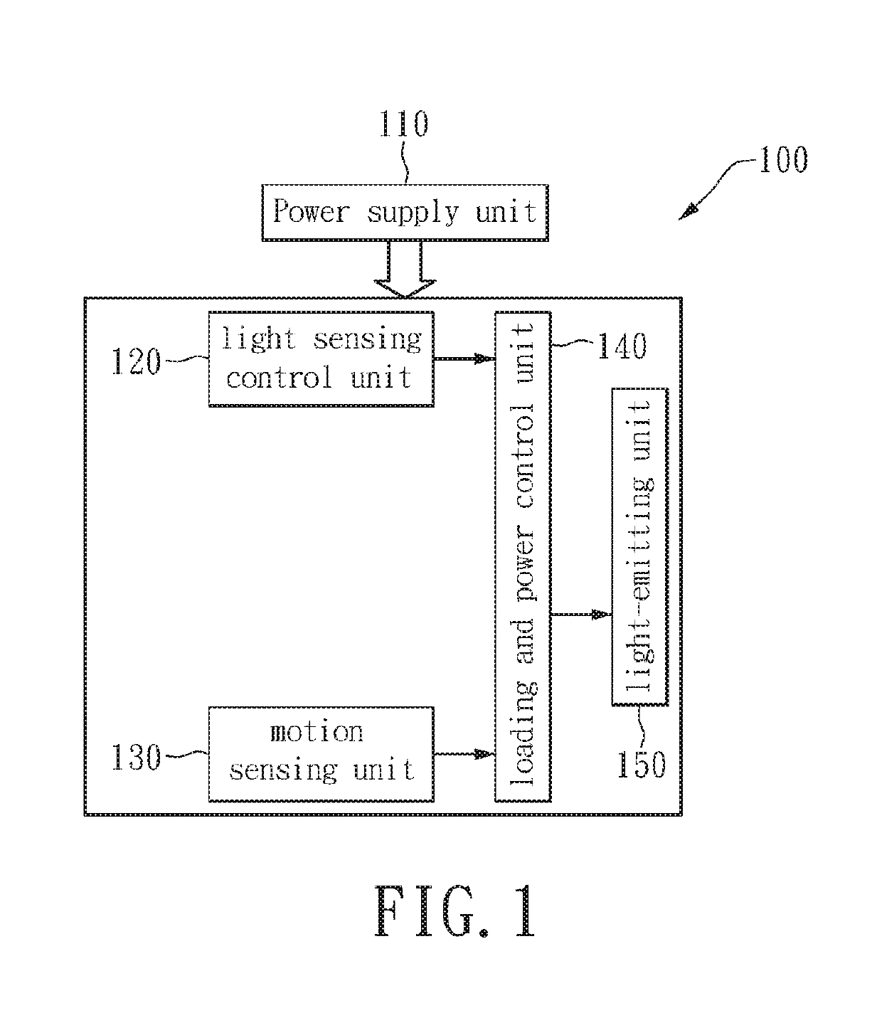
[0036]Refer to FIG. 1, which schematically illustrates a block diagram of a two-level LED security light in accordance to the first exemplary embodiment of the present disclosure. A two-level LED security light (herein as the lighting apparatus) 100 includes a power supply unit 110, a light sensing control unit 120, a motion sensing unit 130, a loading and power control unit 140, and a light-emitting unit 150. The power supply unit 110 is used for supplying power required to operate the system, wherein the associated structure includes the known AC / DC voltage converter. The light sensing control unit 120 may be a photo resistor, which may be coupled to the loading and power control unit 140 for determining daytime or nighttime in accordance to the ambient light. The motion sensing unit 130 may be a passive infrared sensor (PIR), which is coupled to the loading and power control unit 140 and is used to detect intrusions. When a person is entering a predetermined detection zone of the...

second exemplary embodiment

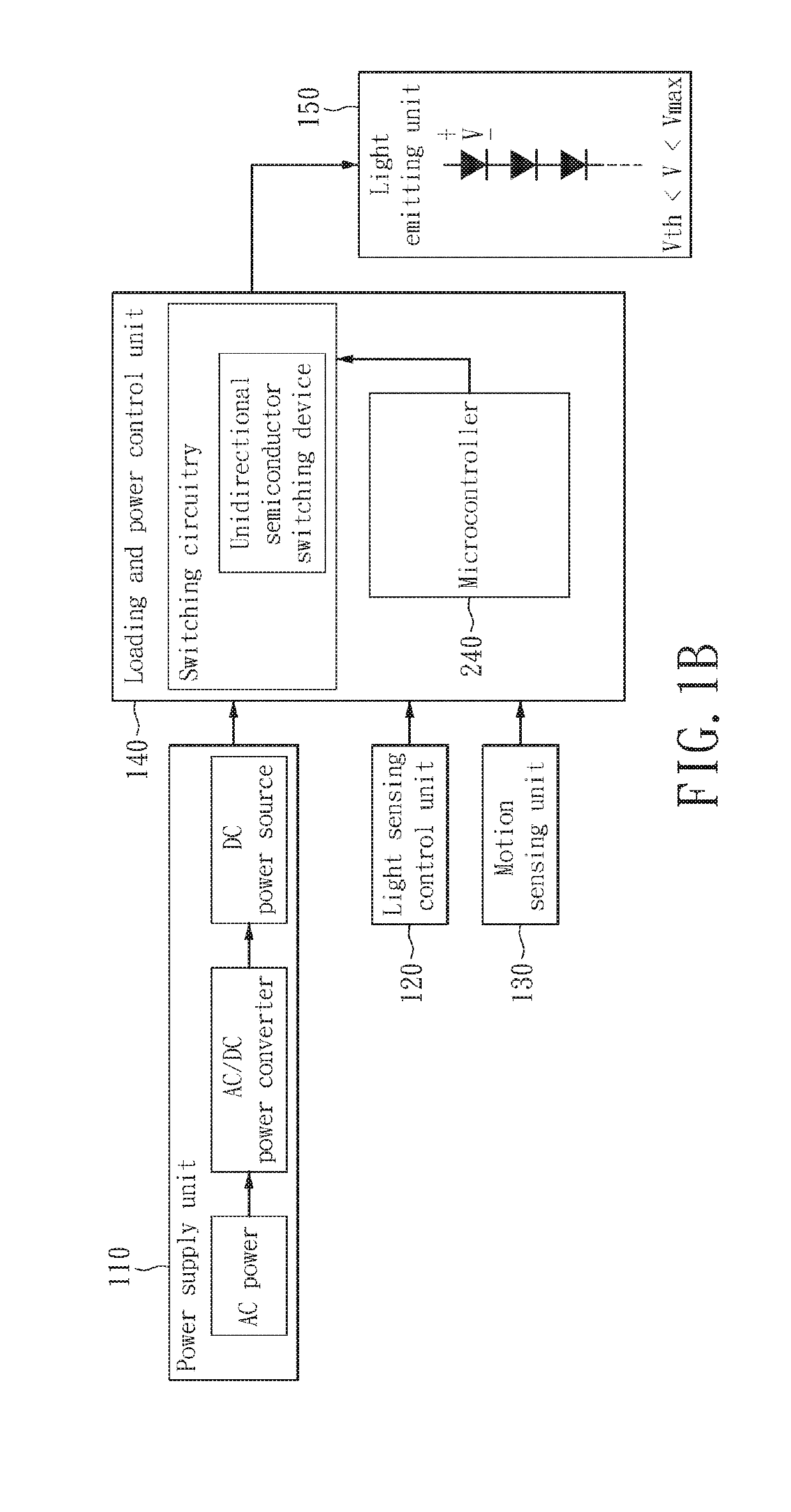
[0043]Refer again to FIG. 1, wherein the illumination variations of the light-emitting unit 150 may be implemented through the number of light-source loads being turned on to generate more than two levels of illumination. The lighting apparatus 100 in the instant exemplary embodiment may be through turning on a portion of LEDs or all the LEDs to generate a low and a high level of illuminations.

[0044]Refer to FIG. 3A concurrently, which illustrates a schematic diagram of a two-level LED security light 100 in accordance to the second exemplary embodiment of the present disclosure. The main difference between FIG. 3A and FIG. 2A is in the light-emitting unit 350, having three series-connected LEDs L1˜L3 and NMOS transistors Q1 and Q2. The LEDs L1˜L3 are series connected to the transistor Q1 at same time connected between the DC source and a constant electric current control circuit 310. Moreover, transistor Q2 is parallel connected to the two ends associated with LEDs L2 and L3. The ga...

third exemplary embodiment

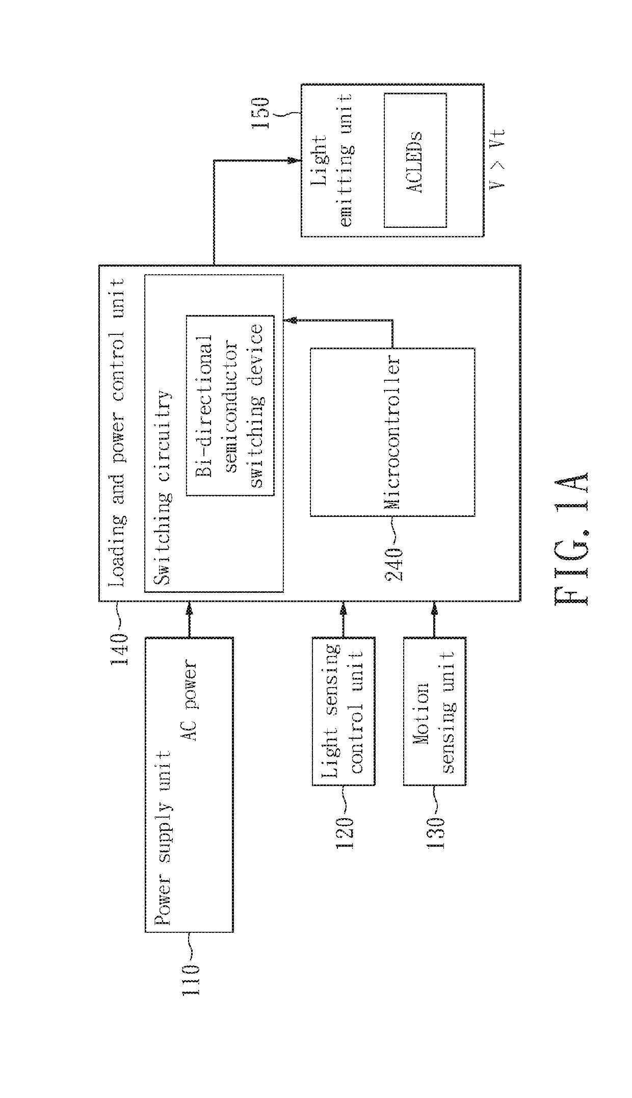
[0050]Refer back to FIG. 1, wherein the light-emitting unit 150 may include one or more parallel-connected alternating current (AC) LEDs. A phase controller is coupled between the described one or more parallel-connected ACLEDs and AC power source. The loading and power controller 140 in the instant exemplary embodiment may through the phase controller adjust the average power of the light-emitting unit 150 so as to generate variations in the low level and the high level illuminations.

[0051]Refer to FIG. 4A, which illustrates a schematic diagram of a two-level LED security light 100 in accordance to the third exemplary embodiment of the present disclosure. The main difference between FIG. 4A and FIG. 3 is in that the light-source load is an ACLED, which is coupled to the AC power source, and further the light-emitting unit 450 is connected to a phase controller 451. The phase controller 451 includes a bi-directional switching device 452, here, a triac, a zero-crossing detection circ...


PUM


Abstract

A security light technology to configure an automatically setting timer used for selecting and operating a light-on duration activated by a motion sensor is disclosed. The disclosed uses a shutoff transition mode to eliminate a hassle or hardship caused by an unexpected “shutoff” of illumination. The shutoff transition mode also serves a communication interface between the motion sensor and an occupant remaining in a detection space such that the occupant can interrupt the shutoff transition mode. The disclosed uses a software algorithm to detect and learn the motion characteristics of occupants in the detection space and thereby to automatically set a timer to operate the light-on duration triggered by a motion intrusion. The disclosed also teaches a dual mode motion sensing light configured with a short timer to manage a pathway illumination and a long timer to manage an occupancy illumination bridged by the shutoff transition mode.

Description

CROSS-REFERENCE TO RELATED APPLICATIONS[0001]This Application is a continuation in part application of prior application Ser. No. 16 / 201,219 filed on Nov. 27, 2018, currently pending, which is a continuation application of prior application Ser. No. 15 / 856,468 filed on Dec. 28, 2017, currently pending, which is a continuation application of prior application Ser. No. 15 / 637,175 filed on Jun. 29, 2017, issued as U.S. patent Ser. No. 10 / 165,643 on Dec. 25, 2018, which is a continuation application of prior application Ser. No. 15 / 230,752 filed on Aug. 8, 2016, issued as U.S. Pat. No. 9,743,480 on Aug. 22, 2017, which is a continuation application of prior application Ser. No. 14 / 478,150 filed on Sep. 5, 2014, issued as U.S. Pat. No. 9,445,474 on Sep. 13, 2016, which is a continuation application of prior application Ser. No. 13 / 222,090 filed on Aug. 31, 2011, issued as U.S. Pat. No. 8,866,392 on Oct. 21, 2014.BACKGROUND1. Technical Field[0002]The present disclosure relates to a lighti...

Claims


Application Information

Patent Timeline
Patent Type & Authority Applications(United States)
IPC IPC(8): H05B33/08F21S9/03F21V17/02G08B5/36G08B13/189G08B15/00H02J7/35H05B37/02H05B39/04H05B44/00F21Y115/10G08B13/00
CPCH05B33/0854F21S9/03H05B33/0872F21V17/02G08B5/36G08B13/1895G08B15/00G08B15/002H05B39/044H05B39/042H05B37/0281H05B37/0227H05B37/0218H05B37/02H05B33/0827H05B33/0824H05B33/0818H05B33/0815H05B33/0809H05B33/083H02J7/35Y02B20/46F21Y2115/10G08B13/00G08B13/189Y02B20/40Y02B20/44H05B45/20H05B45/44H05B47/11H05B47/16Y02B20/00H05B47/17H05B47/115H05B45/12H05B45/46H05B45/48
Inventor CHEN, CHIA-TEH
Owner VAXCEL INT
Why Eureka
Try Eureka