Roof cover fastener

a technology for fasteners and roof covers, applied in the field of fasteners, can solve the problems of limited value of withdrawal resistance, awkward installation and installation of auger screw fasteners that claim not to require pre-drilling, and low commercial success of these applications, and achieve the effect of less labor

Active Publication Date: 2019-05-16
DSCCELCORE
View PDF7 Cites 10 Cited by
  • Summary
  • Abstract
  • Description
  • Claims
  • Application Information

AI Technical Summary

Benefits of technology

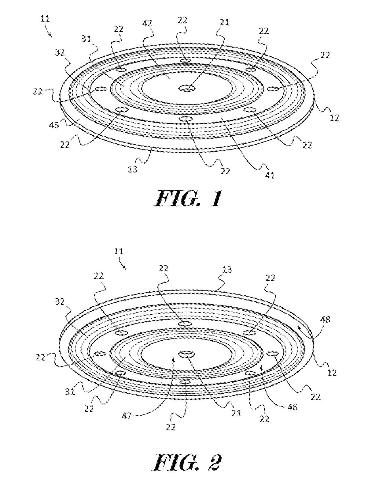
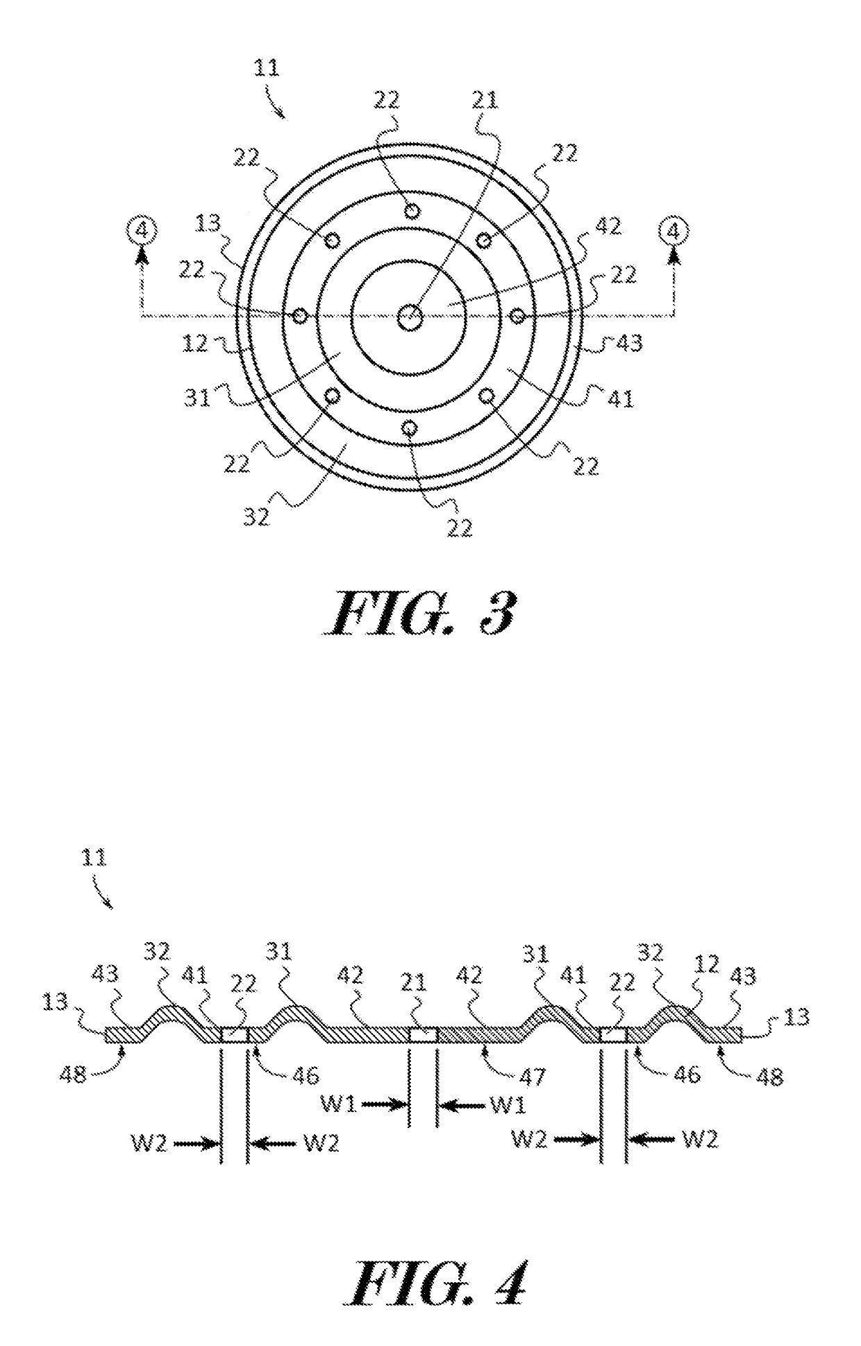
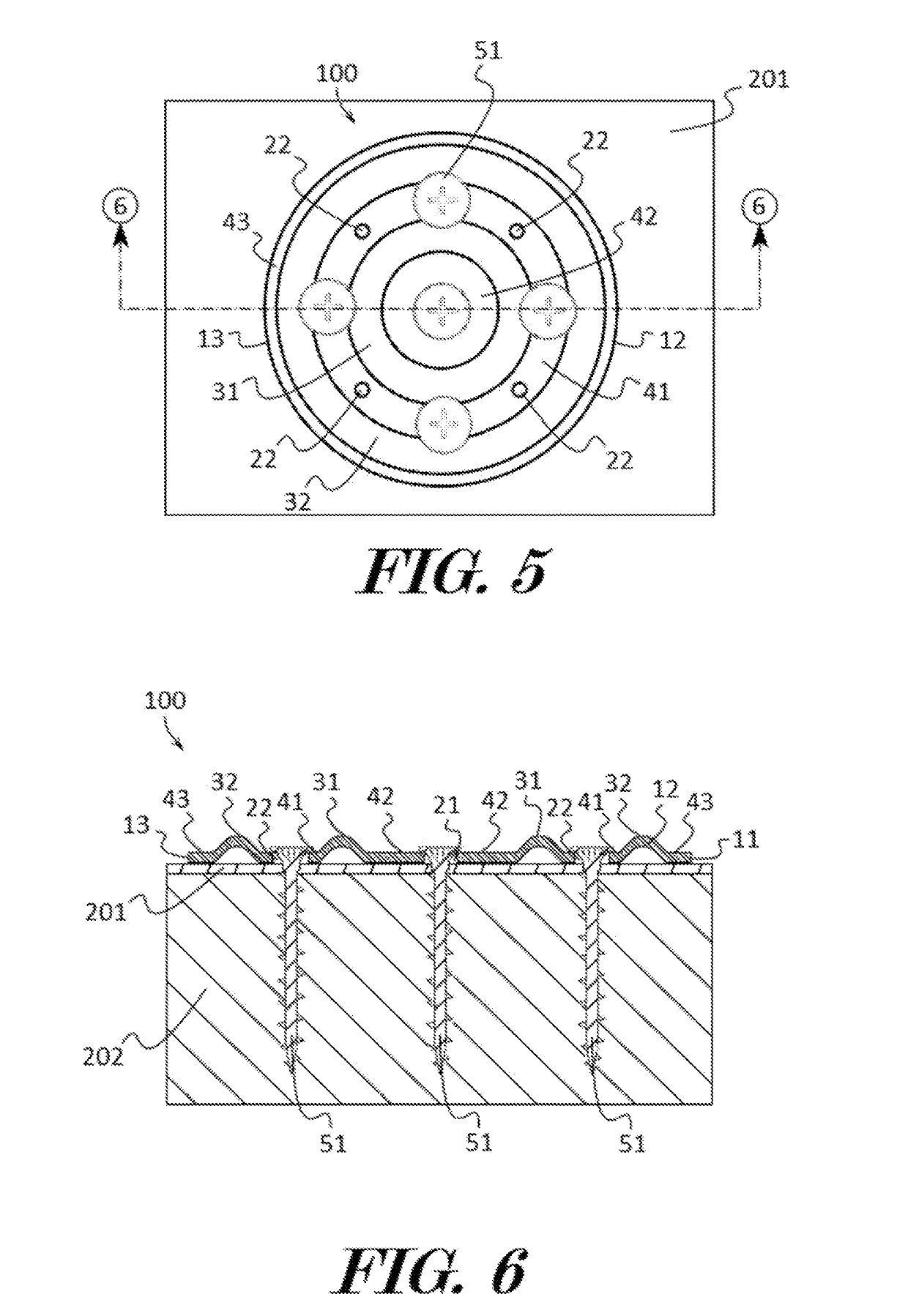
[0005]A roof cover fastener which attaches roof materials to roof deck materials, such as lightweight insulating concrete and other nail-able roof deck materials, is provided. The roof cover fastener may be used for a plurality of roofing and construction purposes including to secure layers of roofing, insulation, or recovery board to the parent deck which would not by themselves provide a water proof layer of construction. The roof cover fastener may be installed without impact and does not require pre-drilling of the roof materials for proper attachment making them a less labor intensive and a more favorable option. In some embodiments, a roof cover fastener may include a cover plate having a planar body with a perimeter. A central aperture may be disposed centrally in the body. A first annular rib may be formed into the body and may encircle the central aperture. A second annular rib may be formed into the body and may encircle the first annular rib. A first channel may separate the first annular rib from the second annular rib, and the first annular rib and second annular rib may extend above the first channel. One or more medial apertures may be disposed in the channel between the first annular rib and the second annular rib.

Problems solved by technology

Auger screw type fasteners are also an available option but have found minimal commercial success in these applications as they often require pre-drilling for proper installation.
Auger screw fasteners that claim not to require pre-drilling are awkward and cumbersome to install.
They also utilize a single, relatively large diameter auger resulting in a limited value of withdrawal resistance.

Method used


Image

  • Roof cover fastener
  • Roof cover fastener
  • Roof cover fastener

Examples


Embodiment Construction

[0037]The terminology used herein is for the purpose of describing particular embodiments only and is not intended to be limiting of the invention. As used herein, the term “and / or” includes any and all combinations of one or more of the associated listed items. As used herein, the singular forms “a,”“an,” and “the” are intended to include the plural forms as well as the singular forms, unless the context clearly indicates otherwise. It will be further understood that the terms “comprises” and / or “comprising,” when used in this specification, specify the presence of stated features, steps, operations, elements, and / or components, but do not preclude the presence or addition of one or more other features, steps, operations, elements, components, and / or groups thereof.

[0038]Unless otherwise defined, all terms (including technical and scientific terms) used herein have the same meaning as commonly understood by one having ordinary skill in the art to which this invention belongs. It wi...


PUM


Abstract

A roof cover fastener may include a cover plate having a planar body with a perimeter. A central aperture may be disposed centrally in the body. A first annular rib may be formed into the body and may encircle the central aperture. A second annular rib may be formed into the body and may encircle the first annular rib. A first channel may separate the first annular rib from the second annular rib. A medial aperture may be disposed in the channel between the first annular rib and the second annular rib. Optionally, the fastener may also include an auger element having a first end and a second end. A head may be coupled to the first end, and a tip may be coupled to the second end. A thread crest with a thread root may extend from the second end towards the first end.

Description

CROSS REFERENCE TO RELATED APPLICATIONS[0001]This application is a continuation-in-part of U.S. Non-Provisional application Ser. No. 15 / 396,744, filed on Jan. 2, 2017, entitled “ROOF COVER FASTENER”, which claims the benefit of U.S. Provisional Patent Application Ser. No. 62 / 274,497, filed on Jan. 4, 2016, entitled “ROOF COVER FASTENER”, the entire disclosures of which are incorporated by reference herein.FIELD OF THE INVENTION[0002]This patent specification relates to the field of fasteners. More specifically, this patent specification relates to fasteners for lightweight insulating concrete and other nail-able roof deck materials.BACKGROUND[0003]Lightweight insulating concrete is a type of cast in place roof deck used in low slope roof designs. Many types of roofing materials used to waterproof, insulate, and / or re-cover these roof deck installations require fastener attachment for adequate wind uplift resistance. Currently, the most common type of fasteners used to attach roofing...

Claims


Application Information

Patent Timeline
Patent Type & Authority Applications(United States)
IPC IPC(8): F16B25/00F16B25/10F16B43/00E04D3/36
CPCF16B25/0031F16B25/103F16B43/00E04D3/36E04D3/3606E04D5/145
Inventor MAC DONALD, WILLIAM R.GARRIGUS, PETER C.KRUEGER, DEREK J.
Owner DSCCELCORE
Why Eureka
Try Eureka