Centrifugal positive blocking brake for shutter drives and shutter drives using the same

a technology of shutter drive and centrifugal force, which is applied in the direction of electrical equipment, dynamo-electric machines, building components, etc., can solve the problems of requiring considerable mounting space, generating considerable switching noise when actuated, and consuming additional energy of shutter drive with active electromagnetic or electromechanical brake, etc., to achieve fast and low-noise start, good centring

Active Publication Date: 2019-05-16
JOHNSON ELECTRIC SA
View PDF0 Cites 4 Cited by
  • Summary
  • Abstract
  • Description
  • Claims
  • Application Information

AI Technical Summary

Benefits of technology

[0016]Particularly good centring and thus a very low-noise embodiment of the centrifugal positive blocking brake for shutter drives can be achieved if the abutment is wedge-shaped or cone-shaped as a three-point abutment in the turntable.
[0017]In order to bring about a very fa

Problems solved by technology

Shutter drives with active electromagnetic or electromechanical brakes consume additional energy and generate considerable switching noise when actuated.
Generally, such brakes are not used for stopping a rotational speed strongly or even rigidly, but

Method used


Image

  • Centrifugal positive blocking brake for shutter drives and shutter drives using the same
  • Centrifugal positive blocking brake for shutter drives and shutter drives using the same
  • Centrifugal positive blocking brake for shutter drives and shutter drives using the same

Examples


Embodiment Construction

[0023]Various embodiments of the present invention are described, by way of example only, with reference to the drawings, in which identical or related structures, elements, or parts may be labeled with the same reference numerals throughout the figures. Dimensions of components and features shown in the figures are generally chosen for convenience and clarity of presentation and are not necessarily to scale.

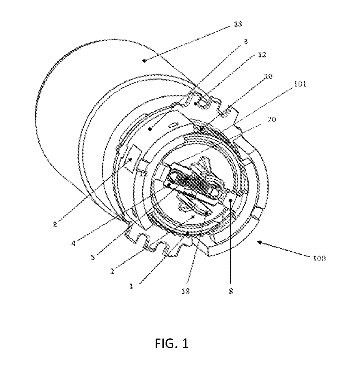
[0024]FIG. 1 shows the construction of a centrifugal positive blocking brake 100 in an oblique 3D view. A turntable 2 is coupled with a drive shaft 7 of a drive motor 6 and a groove-like recess 20 is formed in the turntable 2. A central spring element 4 with a preloaded spring 5 disposed inside is centrifugally guided in this groove-like recess of the turntable 2. The central spring element 4 consists of the spring 5 and two embracing spring forks 17, in which the spring 5 is fastened. The spring 5 is radially guided by means of two opposite embracing spring forks 17 which are m...


PUM


Abstract

The invention concerns a centrifugal positive blocking brake for shutter drives. The brake includes centrifugal blocks, central spring element, and a drive motor comprising a drive shaft. A turntable is coupled with the drive shaft. The central spring element having a preloaded spring is centrifugally guided in a recess of the turntable. Either side of the spring is connected with a radially movable engaging tab element. Two different radially acting abutments are disposed on the central spring element and are movable towards recess. The engaging tab element has at least one engaging tab pointing radially inwards. The centrifugal block is attached to the engaging tab element. In the de-energized state of the drive motor, the engaging tab elements together with the centrifugal blocks disposed on them engage into detents of a frame-fixed detent disc with at least one engaging tab in a frictionally and positively locking manner. When voltage is applied and the drive motor starts, the engaging tabs disengage, the individual centres of mass of the central spring element, preloaded spring, the engaging tab element, the engaging tab, and two centrifugal block parts are on one symmetry axis. This invention creates a centrifugal positive blocking brake which is small in size and constructively simple and causes locking of the shutter when de-energized.

Description

CROSS REFERENCE TO RELATED APPLICATION[0001]This application claims the benefit of German Patent Application Serial No. 10 2017 126 807.3 having a filing date of Nov. 15, 2017. The entire content of the aforementioned is hereby incorporated by reference for all purposes.FIELD OF THE INVENTION[0002]The invention relates to a centrifugal positive blocking brake for shutter drives which, when at rest, generates a sufficient braking and holding torque on the drive, locks the shutter.BACKGROUND OF THE INVENTION[0003]In principle, a great variety of different individual technical solutions are known as active or also as passive braking systems for shutter drives. Shutter drives with active electromagnetic or electromechanical brakes consume additional energy and generate considerable switching noise when actuated. Furthermore, they also need a relatively large mounting space as can be seen, e.g. from EP 000 0002 234 245 and DE 20 2005 007 921. The advantage of passively acting braking sys...

Claims


Application Information

Patent Timeline
IPC IPC(8): F16D63/00F16D59/00
CPCF16D63/006F16D59/00F16D51/18H02K7/102H02K11/21E06B9/72E06B9/90E06B2009/807F16D49/16
Inventor WAHRISCH, STEN
Owner JOHNSON ELECTRIC SA
Why Eureka
Try Eureka