Short latency fast retransmission triggering

a retransmission mechanism and short technology, applied in the field of short latency fast retransmission triggering, can solve the problems of not being able to configure a mobile terminal, not being able to find a spectrum band which is wide enough for the lte-advanced system, and being unable to use a mobile terminal. rlc layer retransmission mechanism may therefore seem superfluous,

Active Publication Date: 2019-05-16
PANASONIC INTELLECTUAL PROPERTY CORP OF AMERICA
View PDF13 Cites 9 Cited by
  • Summary
  • Abstract
  • Description
  • Claims
  • Application Information

AI Technical Summary

Benefits of technology

[0169]Non-limiting and exemplary embodiments provide an improved transmission protocol operation for uplink data packet transmissions for a user equipment.

Problems solved by technology

Nowadays, the lack of radio spectrum has become a bottleneck of the development of wireless networks, and as a result it is difficult to find a spectrum band which is wide enough for the LTE-Advanced system.
It may currently not be possible to configure a mobile terminal with more uplink component carriers than downlink component carriers.
The use of a retransmission mechanism in the RLC layer may therefore seem superfluous at first.
However, this is not the case, and the use of both RLC- and MAC-based retransmission mechanisms is in fact well motivated by the differences in the feedback signaling.
In Unacknowledged Mode data delivery is not guaranteed since no retransmission protocol is used.
Therefore, if the RLC status report is delayed, the transmission window cannot be advanced and the transmission might get stuck.
However, with respect to further improvements specifically targeting the delays in the system little has been done.
During TCP slow start the performance is latency limited.
Various pre-scheduling strategies can be used to lower the latency to some extent, but similarly to shorter Scheduling Request (SR) interval introduced in Rel-9, they do not necessarily address all efficiency aspects.

Method used


Image

  • Short latency fast retransmission triggering
  • Short latency fast retransmission triggering
  • Short latency fast retransmission triggering

Examples


Embodiment Construction

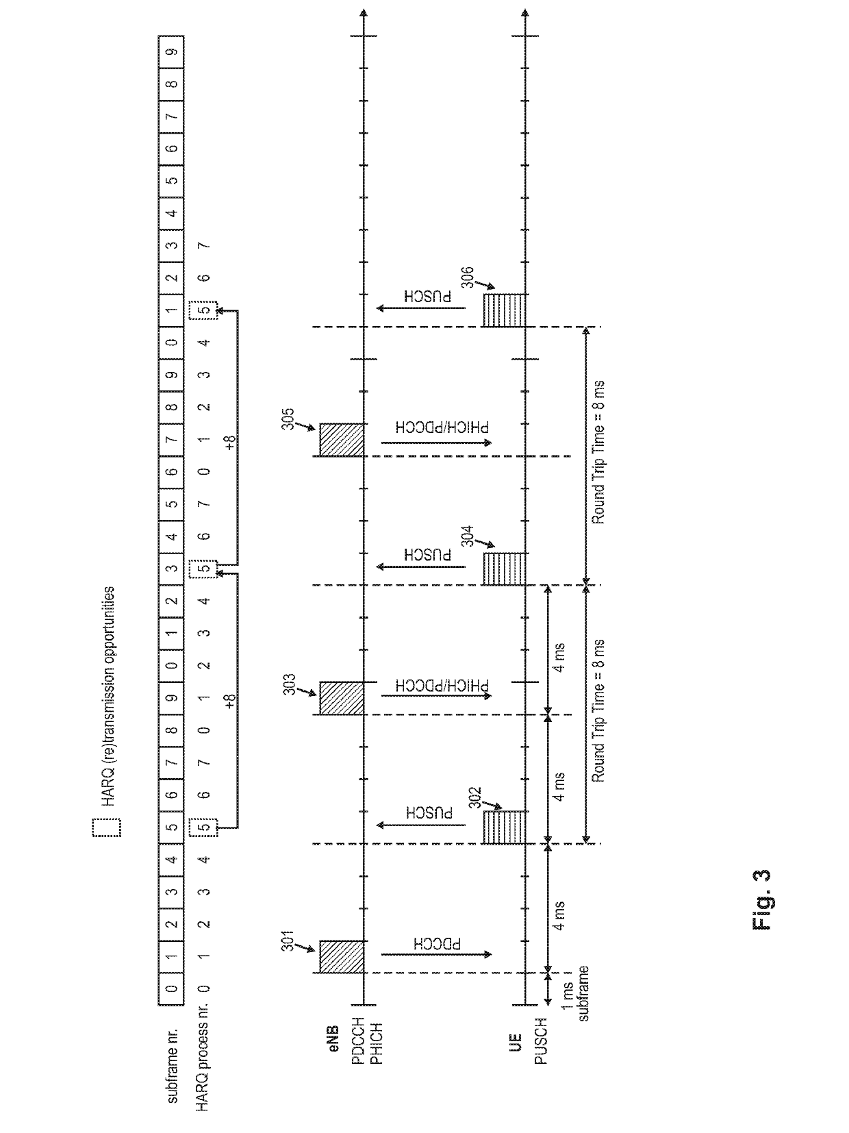
[0186]As can be seen from FIG. 3 and the description thereof in the background section, there is currently a delay of 4 ms between a PDCCH / PHICH and a corresponding PUSCH uplink transmission. This delay is mainly caused due to the processing that needs to be done at the UE side, including the detection of PDCCH / PHICH as well as the coding chain and physical channel processing steps outlined above. Even though this latency of 4 ms could be reduced by shortening the TTI as is being discussed within the scope of the above-described Short Latency study item, the main savings in time would be due to the smaller transport block sizes and a potentially improved hardware / software design that allows faster processing. Nevertheless, the savings are still bounded by the need for processing all the functional blocks in the transmission chain as outlined above, even for a retransmission, especially when a different RV is used for a retransmission compared to the previous transmission of the same...


PUM


Abstract

The invention relates to an improved transmission protocol for uplink data packet transmission in a communication system. A receiver of a user equipment receives a Fast Retransmission Indicator, referred to as FRI. The FRI indicates whether or not a base station requests a retransmission of a previously transmitted data packet. A transmitter of the user equipment retransmits the data packet using the same redundancy version as already used for the previous transmission of the data packet.

Description

BACKGROUNDTechnical Field[0001]The present disclosure relates to methods for operating a transmission protocol for uplink data packet transmission in a communication system. The present disclosure is also providing the user equipment and base station for participating in the methods described herein.Description of the Related Art[0002]Long Term Evolution (LTE)[0003]Third-generation mobile systems (3G) based on WCDMA radio-access technology are being deployed on a broad scale all around the world. A first step in enhancing or evolving this technology entails introducing High-Speed Downlink Packet Access (HSDPA) and an enhanced uplink, also referred to as High Speed Uplink Packet Access (HSUPA), giving a radio access technology that is highly competitive.[0004]In order to be prepared for further increasing user demands and to be competitive against new radio access technologies, 3GPP introduced a new mobile communication system which is called Long Term Evolution (LTE). LTE is designe...

Claims


Application Information

Patent Timeline
Patent Type & Authority Applications(United States)
IPC IPC(8): H04L1/18H04W52/48
CPCH04L1/1816H04L1/1896H04W52/48H04L1/1822H04L1/1864H04L1/1854H04L1/1819H04L1/1607H04L1/0003H04L1/0009H04L12/1872H04L1/00H04L1/18
Inventor GOLITSCHEK EDLER VON ELBWART, ALEXANDERHORIUCHI, AYAKOWANG, LILEI
Owner PANASONIC INTELLECTUAL PROPERTY CORP OF AMERICA
Why Eureka
Try Eureka