
OLED drive power device and OLED television

a technology of drive power and oled television, which is applied in the direction of static indicating devices, television systems, instruments, etc., can solve the problems of excessive power board size and large power board size, and achieve the effect of reducing power board size, reducing power supply cost and simplifying circui

Active Publication Date: 2019-05-16
SHENZHEN SKYWORTH RGB ELECTRONICS CO LTD
View PDF32 Cites 9 Cited by
  • Summary
  • Abstract
  • Description
  • Claims
  • Application Information

AI Technical Summary

Benefits of technology

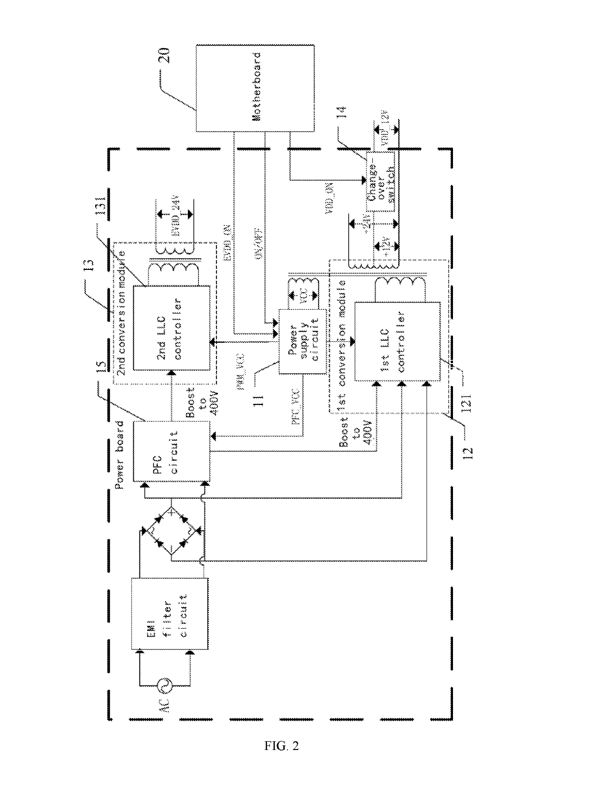
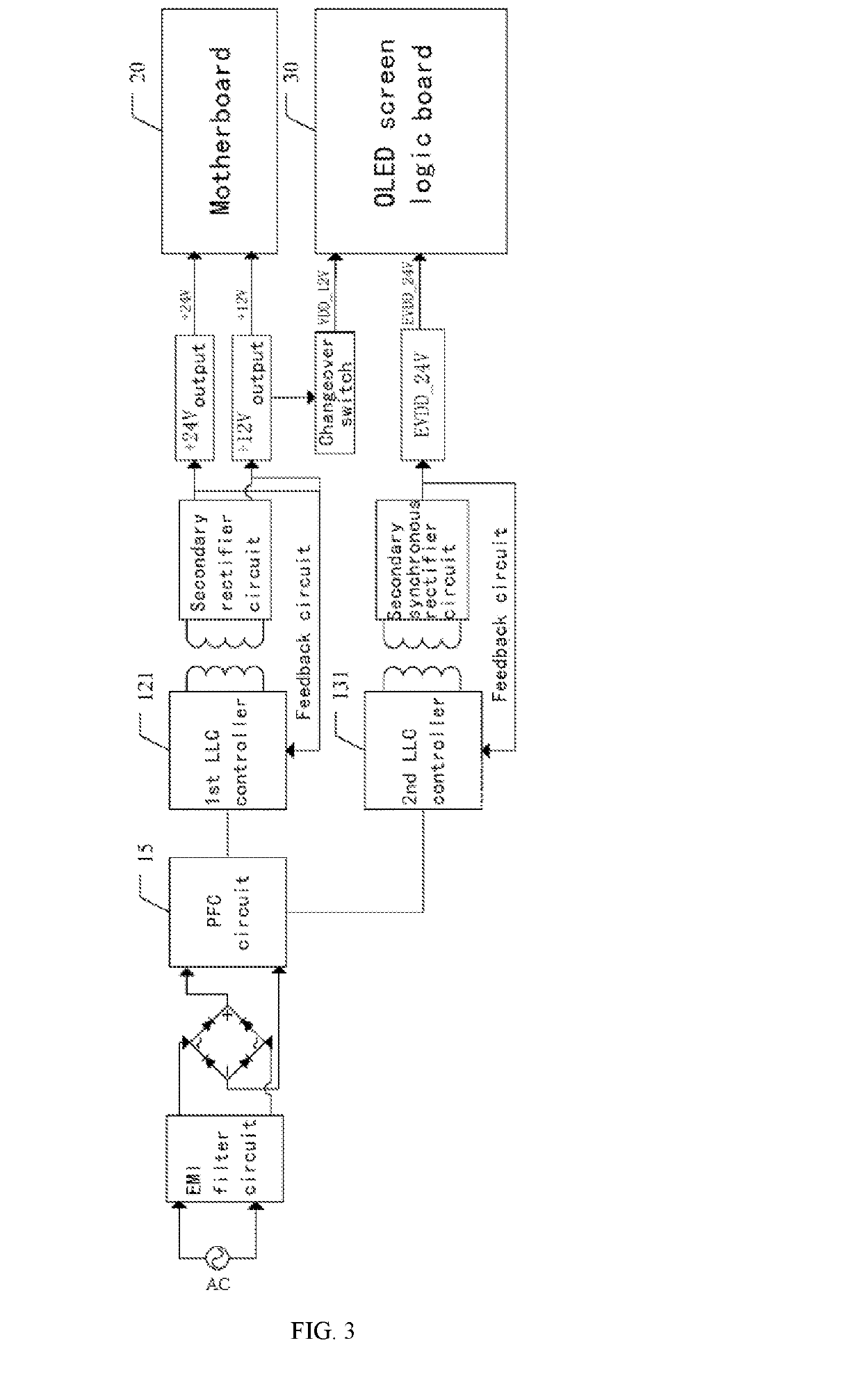
The present invention provides an OLED drive power device and OLED television by redesigning the architecture of the power boards, simplifying the circuit, reducing the size of the power board, and lowering the cost of power supply. The power supply circuit starts the PFC circuit when powered on and converts high-voltage direct current into a high-quality direct current and voltage before supplying power to the motherboard and the OLED screen logic board. The motherboard outputs a second enable signal after a certain time period, and the power supply circuit controls the second conversion module to convert the high-voltage direct current into the second enable voltage before powering up the OLED screen. The OLED screen turns on with a high-quality voltage and a time sequence of power output. This invention solves the contradiction between the OLED's light and thin features and the power board's excessive size and reduces the cost of power supply, making it more accessible for the OLED's popularity.

Problems solved by technology

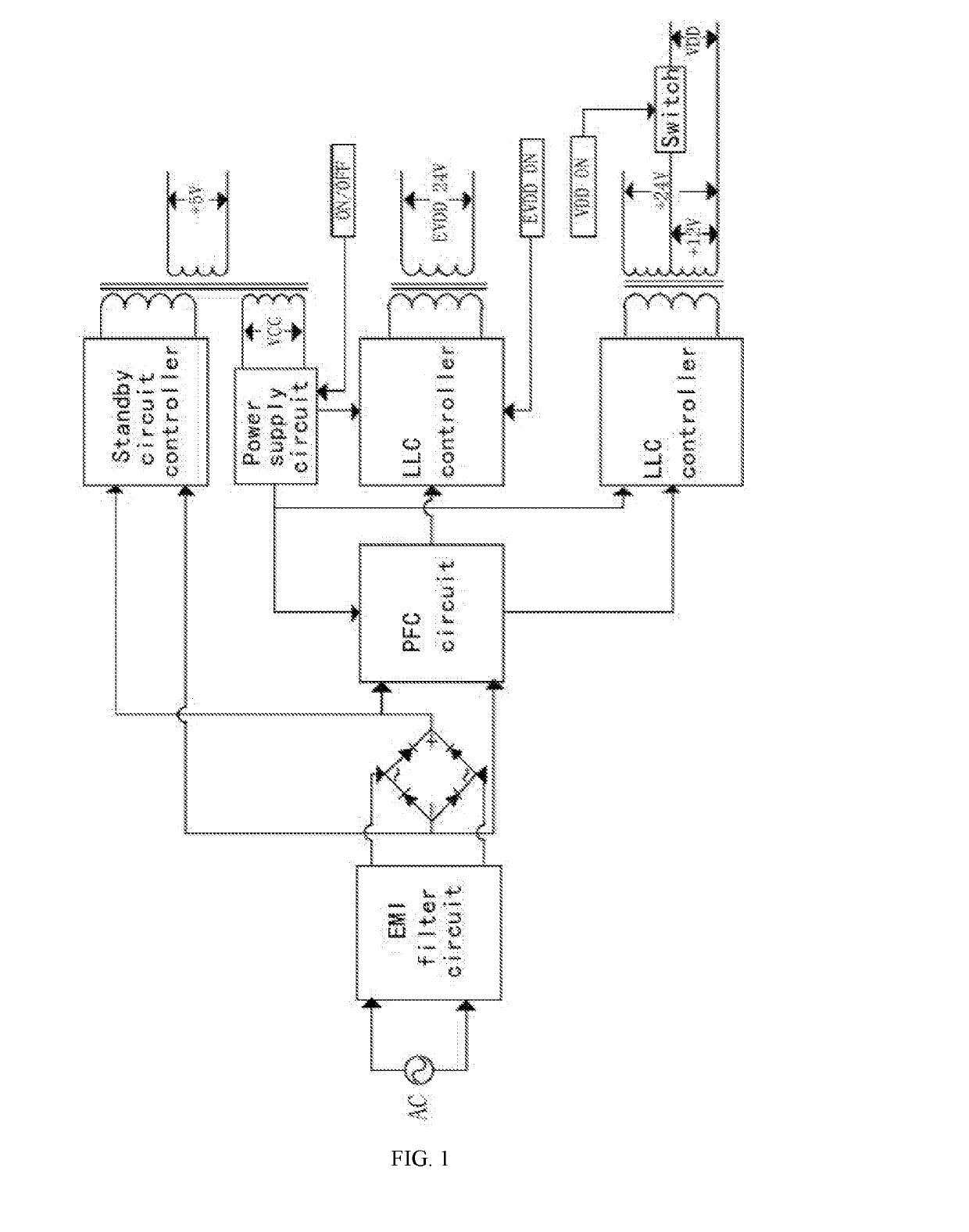
An OLED TV in the present art, comparing to the plurality of TVs using the traditional LCDs and LEDs, has a higher requirement to a time sequence of a power supply, and a larger power, which leads to the size of the power board pretty large.
However, an overall architecture thereof is relatively complicated, resulting in the size of the power board being excessively large, which does not fit to a feature of the OLED of thin and light.

Method used


Image

  • OLED drive power device and OLED television
  • OLED drive power device and OLED television
  • OLED drive power device and OLED television

Examples


Embodiment Construction

[0034]According to the defects in the prior art that an OLED power architecture is complicated, a power board has an excessive large size, the purpose of the present invention is providing an OLED drive power device and an OLED television, by redesigning an architecture of the power board, a standby circuit is omit, a circuit is simplified, that not only satisfies the requirement of an OLED on a stability and a time sequence of a power output, but also successfully reduces a size of the power board, having perfectly solved a contradiction between an OLED having light and thin features and a power board having an excessive size.

[0035]In order to make the purpose, technical solution and the advantages of the present invention clearer and more explicit, further detailed descriptions of the present invention are stated here, referencing to the attached drawings and some embodiments of the present invention. It should be understood that the detailed embodiments of the invention described...


PUM


Abstract

An organic light-emitting diode (OLED) drive power device and OLED television, OLED drive power device comprising power board connected to motherboard and OLED screen logic board, power board having power supply circuit, first conversion module, second conversion module, changeover switch and power factor correction (PFC) circuit thereon; after powered, power supply circuit starts PFC circuit to output high-voltage direct current (HVDC) according to on-off signal output by motherboard, first conversion module converts HVDC into first voltage and second voltage to power motherboard, and first voltage is converted to power OLED screen logic board; after preset time period, HVDC is converted to power OLED screen logic board to light OLED screen. Redesigning architecture of power board eliminates need for standby circuit and streamlines circuits, meets power output stability and timing requirements of OLED, reduces power board size, reduces power cost and benefits OLED popularization.

Description

CROSS-REFERENCES TO RELATED APPLICATIONS[0001]This application is a national application of PCT Patent Application No. PCT / CN2017 / 071023, filed on Jan. 13, 2017, which claims priority to Chinese Patent Application No. 201610863084.0 filed on Sep. 29, 2016. The content of all of which is incorporate herein by reference.FIELD OF THE INVENTION[0002]The present invention relates to the field of technologies on power supplies, and more particularly, to an OLED drive power device and an OLED television.BACKGROUND[0003]An OLED (Organic Light Emitting Diode), due to no backlight required, neither a color filter nor a liquid crystal, and being capable of self-emitting, as well as being superior to a plurality of traditional LCDs and LEDs in a plurality of terms including an image quality, a response speed, a thickness and a viewing angle, thus has quickly become a hot spot for research by different major displayer manufacturers all the world. Following a gradual maturity of OLED technology, ...

Claims


Application Information

Patent Timeline
Patent Type & Authority Applications(United States)
IPC IPC(8): H04N5/63G09G3/3208
CPCH04N5/63G09G3/3208G09G2330/026G09G2330/021H02M1/4208H02M3/33592H02M1/0058H02M1/008H02M1/007
Inventor CAI, SHENGPINGDAI, QIFENGWEI, ZONGWANGZHOU, JIANHUA
Owner SHENZHEN SKYWORTH RGB ELECTRONICS CO LTD
Learn More