Impact energy absorbing apparatus

a technology of energy absorption apparatus and impact, which is applied in the direction of shock absorbers, springs/dampers, elastic dampers, etc., can solve the problems of increasing manufacturing costs, increasing costs, and splitting of joining points, so as to increase the energy required in a folding process, the effect of absorbing energy and stable pipe compression

Inactive Publication Date: 2019-05-23
METAL INDS RES & DEV CENT
View PDF10 Cites 6 Cited by
  • Summary
  • Abstract
  • Description
  • Claims
  • Application Information

AI Technical Summary

Benefits of technology

[0014]Features of the present invention are as follows: When an energy transfer component structure in the present invention is compressed by an impact force, the hollow guiding rod of the force bearing plate trends towards being inserted to the tapered hole of the base. The diameter of the guiding rod is guided by the greatest diameter of the tapered hole and is limited by the smallest diameter of the tapered hole, so that the hollow guiding rod generates a pipe compression effect, and a fixed deformation direction and a stable pipe compression energy absorption effect can be provided. In another aspect, the energy absorbing component jointly formed by a bottom plate and the axial crush component in the present invention also performs an energy absorbing function under an impact fo

Problems solved by technology

This increases costs.
Therefore, there is a risk that a joining point splits and becomes invalid under an impact.
However, the protruding portion and the slope of the sliding pipe component thereof cannot be formed easily geometrically, and manufacturing costs are increased.
Besides, if the protruding portion of the sliding pipe component is excessively high, the pipe component cannot be pressed into the track housing, so that an exposed portion of the pipe component is axially overlapped and deforms in an impact process, and expected outline deformation of the track housing cannot be achieved.
However, after the punched folded

Method used


Image

  • Impact energy absorbing apparatus
  • Impact energy absorbing apparatus
  • Impact energy absorbing apparatus

Examples


Embodiment Construction

[0020]The embodiments of the present invention are described below in detail with reference to drawings. The accompanying drawings are mainly simplified schematic diagrams, and only exemplarily show basic structures of the present invention. Therefore, the drawings show only components related to the present invention. Displayed components are not drawn based on quantities, shapes, sizes, proportions, and the like during implementation, and specifications and sizes thereof during actual implementation are optionally designed, and arrangement and forms of the components thereof may be more complex.

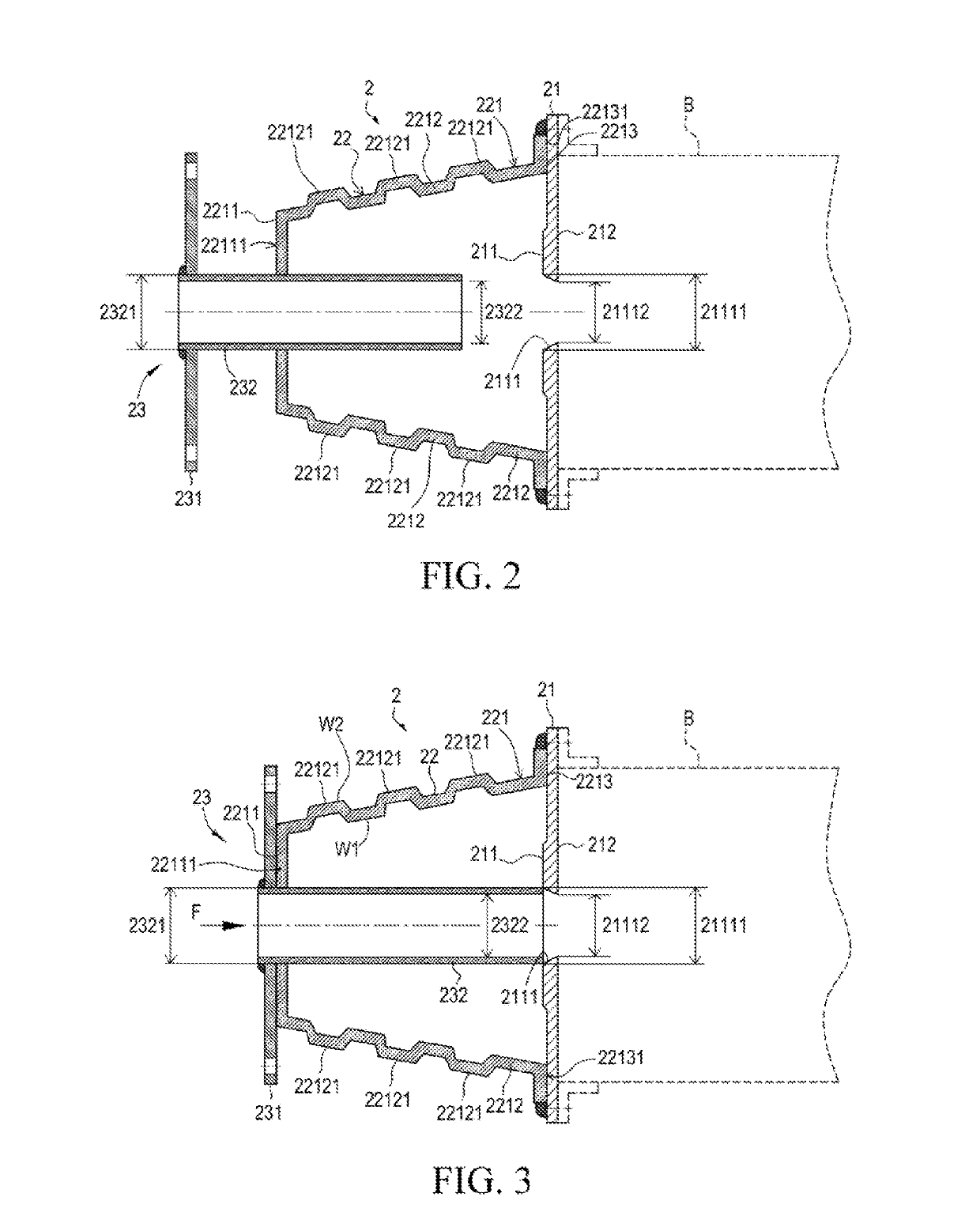
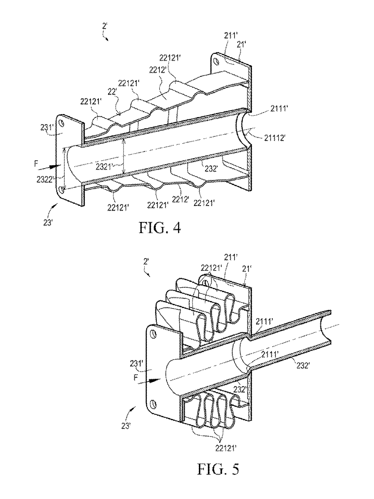
[0021]First, refer to FIG. 2, FIG. 3, FIG. 4, and FIG. 5. An impact energy absorbing apparatus 2 in an embodiment absorbs external impact energy by deformation, to reduce deformation and damage degrees of a protected object B. A structure of the impact energy absorbing apparatus 2 includes: a base 21, an axial crush component 22, and an energy transfer component 23. The base 21 may be faste...


PUM


Abstract

An impact energy absorbing apparatus includes: a base, an axial crush component, a top plate, and an energy transfer component. The base is fastened to a protected object, and a tapered hole is provided on a top surface of the base. A bottom end face of the metal hollow rod of the axial crush component is joined with the top surface of the base. The energy transfer component includes a force bearing plate and a guiding rod extending outwards, where the force bearing plate is superimposed on a top surface of the metal hollow rod, the guiding rod is inserted to a position corresponding to the tapered hole in the metal hollow rod, an outer diameter of the guiding rod is less than a greatest diameter of the tapered hole, an inner diameter of the guiding rod is greater than a smallest diameter of the tapered hole.

Description

BACKGROUNDTechnical Field[0001]The present invention relates to an impact energy absorbing apparatus, and in particular, to an impact energy absorbing apparatus absorbing impact energy by using pipe compression and deformation of a guiding rod, to reduce slanting and deformation of a composition structure in combination with an energy transfer component assembly and an energy absorbing component assembly when an entire structure bears an impact.Related Art[0002]Currently, there are many types of energy absorbing structures applied when vehicles collide and bear an impact, for example, a path-type energy absorbing unit 1 used in a vehicle collision and impact system disclosed in US patent document U.S. Pat. No. 6,231,095 B1, as shown in FIG. 1A and FIG. 1B. The path-type energy absorbing unit 1 may absorb impact energy and prevent or minimize damage of a vehicle framework track 14 under an impact. In a basic embodiment thereof, one end of a pipe 11 is open and welded at a hole 121 of...

Claims


Application Information

Patent Timeline
IPC IPC(8): B60R19/34B60R19/48
CPCB60R19/34B60R19/48B60R2019/005F16F7/12F16F7/123
Inventor TUNG, PEI-CHUNLIN, DIAN-YONGWANG, CHIN-KAIWANG, LI-DE
Owner METAL INDS RES & DEV CENT
Why Eureka
Try Eureka