Method of controlling fuel injection in a reheat combustor for a combustor unit of a gas turbine
- Summary
- Abstract
- Description
- Claims
- Application Information
AI Technical Summary
Benefits of technology
Problems solved by technology
Method used
Image

Examples
Embodiment Construction
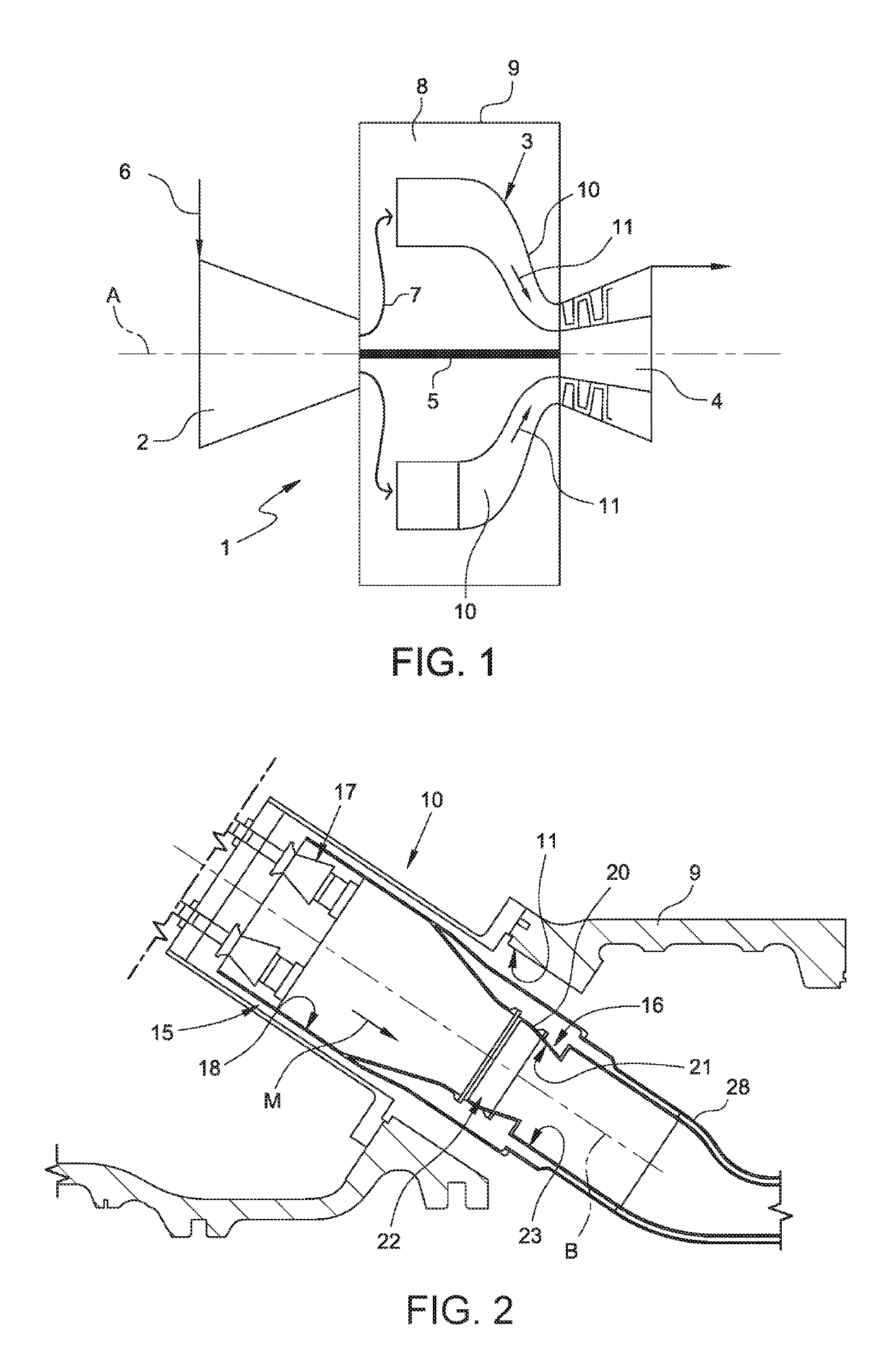
[0038]FIG. 1 is a schematic view of a gas turbine 1 for power plants that can be provided with a reheat combustor according to the present invention.
[0039]Gas turbine 1 comprises a compressor 2, a combustor assembly 3 and a turbine 4. Compressor 2 and turbine 4 have a common axis A and form respective sections of a rotor 5 rotatable about axis A.
[0040]As is known, ambient air 6 enters compressor 2 and is compressed. Compressed air 7 leaves compressor 2 and enters a plenum 8, i.e. a volume defined by an outer casing 9. From plenum 8, compressed air 7 enters combustor assembly 3 that comprises a plurality of can combustors 10 annularly arranged around axis A. Here at least a fuel is injected, and the air / fuel mixture is ignited, producing hot gas 11 that is conveyed to turbine 4.
[0041]As is better shown in FIG. 2, each can combustor 10 is housed in a respective portal hole 11 of the outer casing 9 and has an axis B. Can combustor 10 comprises, in series along gas flow M, a first or pr...
PUM
 Abstract
Description
Claims
Application Information
 - R&D
- Intellectual Property
- Life Sciences
- Materials
- Tech Scout
- Unparalleled Data Quality
- Higher Quality Content
- 60% Fewer Hallucinations
Browse by: Latest US Patents, China's latest patents, Technical Efficacy Thesaurus, Application Domain, Technology Topic, Popular Technical Reports.
© 2025 PatSnap. All rights reserved.Legal|Privacy policy|Modern Slavery Act Transparency Statement|Sitemap|About US| Contact US: help@patsnap.com