Method and apparatus of dead time tuning in an inverter

a technology of inverter and dead time, applied in the field of dead time tuning in inverter, can solve problems such as myriad of problems, and achieve the effects of reducing parasitic inductance, and preventing overload to the input sour

Active Publication Date: 2019-05-23
HONG KONG APPLIED SCI & TECH RES INST
View PDF0 Cites 5 Cited by
  • Summary
  • Abstract
  • Description
  • Claims
  • Application Information

AI Technical Summary

Benefits of technology

[0005]One example embodiment is a method that prevents overload to input source and reduces parasitic inductance in an inverter circuit with dead-time control. The method includes sensing temperatures of a high side device in the inverter circuit with a first sensing capacitor, sensing temperatures of a low side device in the inverter circuit with a second sensing capacitor, changing first dead time intervals by a first delay generator and in response to receiving the temperatures from the first sensing capacitor; changing second dead time intervals by a second delay generator and in response to receiving the temperatures from the second sensing capacitor; preventing overload to the input source and reducing parasitic inductance by connecting the first sensing capacitor between an output of the first delay generator and a ground, and connecting the second sensing capacitor between an output of the second delay generator and the ground. The first dead time intervals correspond to dead times before the high side device is turned on. The second dead time intervals correspond to dead times before the low side device is turned on. The deadtime control includes generating dead times based on the first dead time intervals and the second dead time intervals.
[0006]Another example embodiment is an inverter circuit that prevents overload to input source and reduces parasitic inductance in the inverter circuit. The inverter circuit includes a first sensing capacitor that is thermally connected to a high side device in the inverter circuit, a second sensing capacitor that is thermally connected to a low side device in the inverter circuit, a dead times generation unit that prevents shoot-through currents and reduces body-diode conduction time by generating dead times including first dead time intervals and second dead time intervals for the high side device and the low side device respectively. The dead times generation unit includes a first delay generator that changes the first dead time intervals and a second delay generator. The first sensing capacitor is connected between an output of the first delay generator and a ground. The second sensing capacitor is connected between an output of the second delay generator and the ground. The first dead time intervals correspond to dead times before the high side device is turned on, and the second dead time intervals correspond to dead times before the low side device is turned on.
[0007]Another example embodiment is a method that prevents overload to input source and reduces parasitic inductance in an inverter circuit with deadtime control. The method includes sensing temperatures of at least one high side device in the inverter circuit and temperatures of at least one low side device in the inverter circuit; changing first dead time intervals and second dead time intervals with at least one dead times generation unit and in response to receiving the temperatures of the at least one high side device and the temperatures of the at least one low side device; and preventing shoot-through currents and reducing body-diode conduction time by operating the inverter circuit with dead times within a maximum dead time and a minimum dead time. First dead time intervals correspond to dead times before the at least one high side device is turned on and second dead time intervals that correspond to dead times before the at least one low side device is turned on. The maximum dead time depends on a capacitance of at least one sensing capacitor at a rated temperature and the minimum dead time depends on the capacitance of the at least one sensing capacitor at Curie temperature.

Problems solved by technology

Unfortunately, some inverters are subject to shoot-through current which can cause a myriad of problems.

Method used


Image

  • Method and apparatus of dead time tuning in an inverter
  • Method and apparatus of dead time tuning in an inverter
  • Method and apparatus of dead time tuning in an inverter

Examples


Embodiment Construction

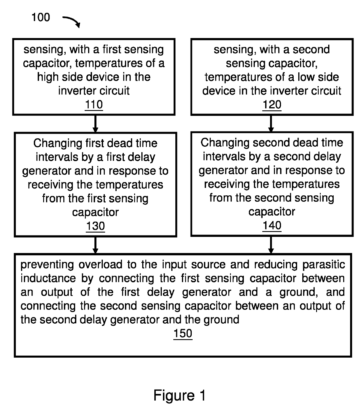
[0015]As used herein, a “body-diode conduction time” is a period that the current flows via the high-resistive parasitic body-diode path paralleled with the device channel when the channels of high side and low side devices in the power inverters are both off, e.g. dead time intervals.

[0016]As used herein and in the claims, “comprising” means including the following elements but not excluding others.

[0017]As used herein, a “Curie temperature” is a threshold temperature at which the positive temperature coefficient material changes its characteristics, e.g. capacitance sharp increase. The characteristic of Curie temperature is utilized to limit the maximum current of power devices, hence prevent shoot through current.

[0018]As used herein, connection by one wire or conductor strip “only” refers to direct connection between the sensing capacitor and the delay generator.

[0019]As used herein, “dead times generation unit” is a circuit that inserts dead times into a pulse width modulator (...


PUM

PropertyMeasurementUnit
resistanceaaaaaaaaaa
undershoot voltageaaaaaaaaaa

Abstract

A method that prevents overload to input source and reduces parasitic inductance in an inverter circuit with dead-time control. A sensing capacitor senses temperatures of transistors in the inverter circuit. A delay generator changes delay times in response to receiving the temperatures of the transistors from the sensing capacitor. A dead time generation unit changes the dead times for the transistors in response to changes in the delay times.

Description

CROSS-REFERENCE TO RELATED APPLICATION[0001]This application is a continuation-in-part application of U.S. Non-provisional application Ser. No. 15 / 459,003 filed on 15 Mar. 2017, which is hereby incorporated by reference herein in its entirety for all purposes.FIELD OF INVENTION[0002]The present invention relates to methods and apparatus that prevent shoot-through current and reduce body-diode conduction time of power devices in an inverter circuit by changing dead times.BACKGROUND OF INVENTION[0003]Power inverters are electronic devices or circuits that change direct current (DC) into alternating current (AC). Inverters play an important role in modern electronics and have wide applications that include uninterruptible power supplies, solar power, induction heating, wireless power transfer, and many other technologies. Unfortunately, some inverters are subject to shoot-through current which can cause a myriad of problems.[0004]New methods and systems that prevent shoot-through curre...

Claims


Application Information

Patent Timeline
Patent Type & Authority Applications(United States)
IPC IPC(8): H02M1/32H02M1/38H02M7/5387G01K7/34
CPCH02M1/32H02M1/38H02M7/53871G01K7/34H02M2001/385H02M1/08H03K17/04206H03K17/0822H03K17/166H03K2017/0806H03K17/00H02M1/385
Inventor LEE, HANG SANGLIU, YAN
Owner HONG KONG APPLIED SCI & TECH RES INST
Why Eureka
Try Eureka