
Method and device for optical examination of transparent bodies

a transparent body and optical examination technology, applied in the field of methods and devices for optical examination of bodies, can solve the problems of inability to distinguish, deformation of optical systems, and inability to distinguish whether an adhering lint is located on the body, and achieves the effect of simple setup

Active Publication Date: 2019-05-30
SCHOTT PHARMA SCHWEIZ AG
View PDF4 Cites 7 Cited by
  • Summary
  • Abstract
  • Description
  • Claims
  • Application Information

AI Technical Summary

Benefits of technology

This patent is about a method to increase the accuracy of measuring and inspecting a body by eliminating blurring effects caused by the body's rotation during image capture. The method uses advanced algorithms to computationally eliminate motion blur from the images, which improves the evaluation of defects. This technique helps to make the inspection process more accurate, reliable, and efficient.

Problems solved by technology

A drawback of the prior art devices and methods is that defects in the optical system, i.e. in the area of the imaging device, can be interpreted as defects in the glass product.
The methods are not adapted to distinguish whether the cause of a defect is in the area of the optical system or in or on the examined body.
This means specifically, for example, that it is not possible to distinguish whether an adhering lint is located on the body or on the lens of the imaging device.
Therefore, it is not possible to distinguish interferences or functional impairments of the associated optical inspection device from defects related to the body to be examined.
Clouds in the glass, for example, may be a contamination of the glass and in this sense are defects that are causally related to the body to be examined.
This inadequate distinction means that the defects analyzed on the glass product have to be significantly greater than the interferences in the system.
However, if the accuracy of the imaging system is intended to be enhanced, this is only possible by reducing interferences in the overall system.
An increase in the accuracy of the method to the order of magnitude of the variations in the glass surface is not possible, since even with a perfect inspection system such interferences would still be interpreted as defects.
Therefore, an improvement in the accuracy of the examination is hardly possible without simultaneously causing a higher false reject caused by interferences in the device itself.
Further drawbacks arise from the fact that further analyzing of defects, for example of the number of defects, is difficult to achieve, and also that the analyzing of certain defects is possible only with reduced probability, for example of cracks which are only visible under specific angles.
However, such an arrangement would usually be more complex, and therefore preference is given to the above-mentioned embodiment with rotating body and stationary imaging device and / or illumination device.
However, the computational evaluation of the obtained images requires rather high computing power of the evaluation unit, since there will be more defects on the images in total and it is necessary to distinguish between defects on the front and the back sides.
This is often system-dependent due to the optical system.
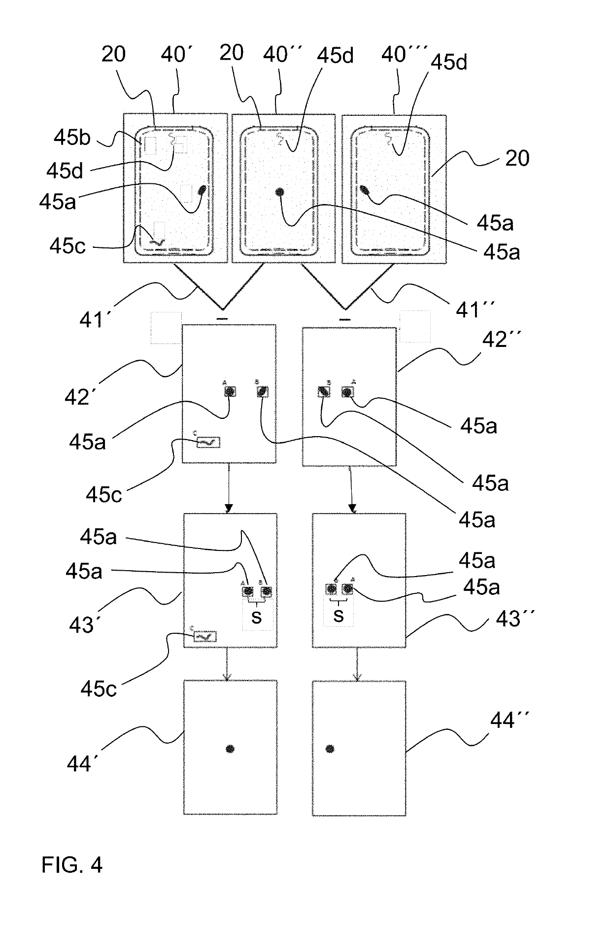
Defects, for example surface damage such as scratches or cracks, but also defects in the volume, such as trapped bubbles in glass or glass ceramic bodies, will cause light / dark deviations in the captured image.

Method used


Image

  • Method and device for optical examination of transparent bodies
  • Method and device for optical examination of transparent bodies

Examples


Embodiment Construction

[0088]In the following detailed description of preferred embodiments, the same reference numerals designate substantially similar components in or on these embodiments, for the sake of clarity. However, for a better understanding of the invention, the preferred embodiments illustrated in the figures are not always drawn to scale.

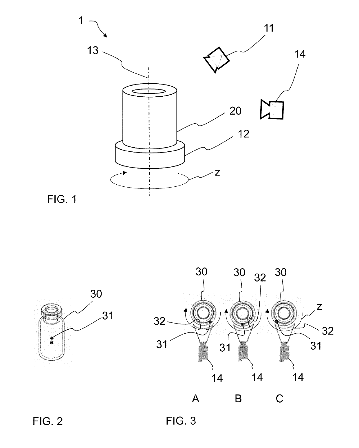
[0089]FIG. 1 schematically shows a portion of an inspection device designated by reference numeral 1 as a whole, for optical examination and inspection of bodies.

[0090]The invention provides an inspection method and an inspection device for quality control of transparent bodies which preferably have a rotationally symmetrical shape. It is particularly useful for the examination of transparent bodies made of plastic, glass, or glass ceramics, which may be solid as well as hollow.

[0091]Preferably, these may be pharmaceutical containers or packaging means, such as glass syringes or glass ampoules. During the inspection, the body to be examined is rotated about ...


PUM


Abstract

A method and a device for optical examination of transparent bodies made of plastic, glass, or glass ceramic are provided. The examination is carried out by contactless detection and measurement of the body using optical imaging devices. For this purpose, a plurality of individual images are taken of the body during the examination in different positions relative to the imaging device, which are subsequently analyzed.

Description

CROSS REFERENCE TO RELATED APPLICATIONS[0001]This application is a continuation of international application PCT / EP2017 / 069259 filed Jul. 31, 2017 which claims benefit under 35 USC § 119 of German Application 102016114190.9 filed Aug. 1, 2016, the entire contents of both of which are incorporated herein by reference.BACKGROUND1. Field of the Invention[0002]The present invention relates to a method and to a device for optical examination of bodies, preferably transparent bodies made of plastics, glass, or glass ceramics. The examination is carried out by contactless detection and measurement of the body using optical imaging devices.2. Description of Related Art[0003]Contactless acquisition of information about diverse types of bodies is of great interest in many fields of science and technology. There is a great variety of applications ranging from geometric detection to the inspection of surfaces of technical products. Non-contact or contactless optical inspection of technical prod...

Claims


Application Information

Patent Timeline
Patent Type & Authority Applications(United States)
IPC IPC(8): G06T7/00G01B11/24G06T7/571G06T5/00H04N5/225H04N5/247H04N23/90
CPCG06T7/001G01B11/24G06T7/571G06T7/97G06T5/003H04N5/2256H04N5/247G06T2207/20224G01N21/90H04N23/56H04N23/90G06T5/73
Inventor KLAGER, CHRISTIANWIRTH, ANDREASTHURK, JURGEN
Owner SCHOTT PHARMA SCHWEIZ AG
Learn More