Ignition coil for internal combustion engine

Active Publication Date: 2019-05-30
DENSO CORP
View PDF3 Cites 2 Cited by
  • Summary
  • Abstract
  • Description
  • Claims
  • Application Information

AI Technical Summary

Benefits of technology

[0010]The ignition coil, as described above, has the closing member which is pressed at the outer periphery of the resinous cylinder against the high-voltage tower, thereby minimizing direct exertion of the pressure, as produced by the press-fit of the closing member in the high-voltage tower, on the high-voltage terminal and the resistor. This enables the outer pressure surface of the resinous cylinder press-fit in the high-voltage tower to have a length increased in the vertical direction, which results in an increase in area of the outer peripheral surface placed in contact with the high -voltage tower. The outer peripheral surface of the resinous cylinder which has an increased area is, therefore, capable of bearing the pressure exerted by the high-voltage tower on the resinous cylinder, thereby ensuring a desired mechanical strength of the high-vo

Problems solved by technology

This may result in a risk that an excessive pressure is exerted by the high-voltage output terminal on both the resistor an

Method used


Image

  • Ignition coil for internal combustion engine
  • Ignition coil for internal combustion engine
  • Ignition coil for internal combustion engine

Examples


first embodiment

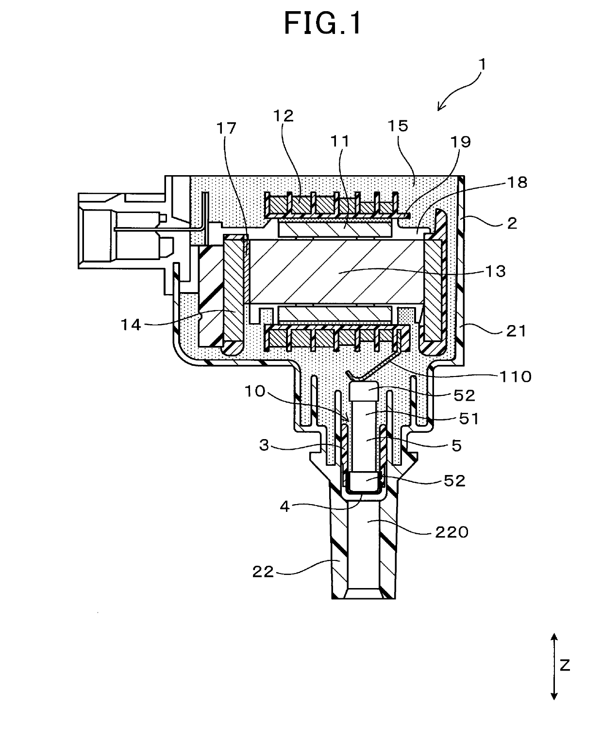
[0046]The ignition coil 1 for internal combustion engines according to the first embodiment will be described below with reference to FIGS. 1 to 6.

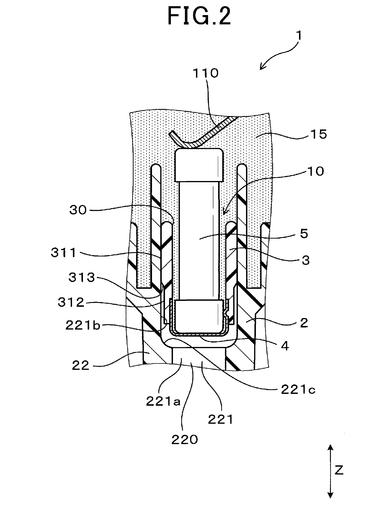
[0047]The ignition coil 1, as clearly illustrated in FIG. 1, includes the primary coil 11, the secondary coil 12, the case 2, the closing member 10, and the filled resin 15. The primary coil 11 and the secondary coil 12 are magnetically coupled together. The case 2 includes the case body 21 in which the primary coil 11 and the secondary coil 12 are disposed and the hollow cylindrical high -voltage tower 22 protruding or extending downward from the case body 21. The closing member 10 is press-fit in the high-voltage tower 22 to close the inside of the high-voltage tower 22. The filled resin 15 is disposed in the case body 21 and hermetically seal the primary coil 11 and the secondary coil 12.

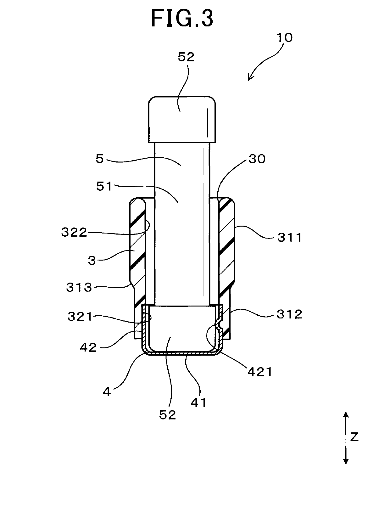
[0048]The closing member 10 includes the resinous cylinder 3, the high-voltage terminal 4, and the resistor 5. The resinous cylinder 3 is made from re...

second embodiment

[0080]FIG. 7 illustrates the closing member 10 according to the second embodiment.

[0081]The high-voltage terminal 4 has the holes 43 formed in the periphery thereof. The holes 43 extend through a thickness of the high-voltage terminal 4 in the radial direction of the high-voltage terminal 4 and lie in a region expanding in the vertical direction Z where the high-voltage terminal 4 and the resinous cylinder 3 are firmly attached to each other. In other words, the holes 43 face a contact of area between the high-voltage terminal 4 and the resinous cylinder 3 in the radial direction of the high-voltage terminal 4. The resinous cylinder 3 is partially disposed in the holes 43.

[0082]Specifically, the holes 43 are, as clearly illustrated in FIG. 8, arranged at three places in the inner periphery of the high-voltage terminal 4 and at equal intervals away from each other in the circumferential direction of the high-voltage terminal 4. All the holes 43 are arranged away from the inner protru...

third embodiment

[0088]FIG. 10 illustrates the closing member 10 according to the third embodiment.

[0089]In a region extending in the vertical direction Z where the high-voltage terminal 4 and the resinous cylinder 3 are firmly attached to each other, the high-voltage terminal 4 has formed on the outer periphery thereof the outer protrusions 423 which bulge outward into the inner periphery of the resinous cylinder 3 in the radial direction thereof.

[0090]The outer protrusions 423 are formed using a press. The outer protrusions 423 are of a semi-spherical shape in cross section. The resinous cylinder 3 has formed in the large-diameter inner surface 321 the recesses 321a firmly attached to the outer protrusions 423. The locations of the outer protrusions 423 of the high-voltage terminal 4 are the same as those of the holes 43 in the second embodiment illustrated in FIGS. 7 to 9.

[0091]Other arrangements are identical with those in the first embodiment.

[0092]The third embodiment offers substantially the ...


PUM


Abstract

An ignition coil for internal combustion engines is provided which includes a primary coil, a secondary coil, a case, a closing member, and a filled resin. The case includes a case body and a high-voltage tower. The closing member is press fit in the high -voltage tower to close the inside of the high-voltage tower. The closing member includes a resinous cylinder, a high-voltage terminal firmly attached to the resinous cylinder, and a resistor fit in the high-voltage terminal. The high-voltage terminal is of a hollow cylindrical shape with a bottom and an upper opening. The closing member has an outer peripheral surface of the resinous cylinder press-fit in the high-voltage tower. This structure minimizes pressure exerted on the resistor and the high-voltage tower to secure a desired degree of durability of the resistor and the high-voltage tower.

Description

CROSS REFERENCE TO RELATED DOCUMENT[0001]The present application claims the benefit of priority of Japanese Patent Application No. 2017-226217 filed on Nov. 24, 2017, the disclosure of which is incorporated herein by reference.BACKGROUND1 Technical Field[0002]This disclosure relates generally to an ignition coil for internal combustion engines.2 Background Art[0003]Japanese Patent First Publication No. 2006-269613 teaches an ignition coil for internal combustion engines which is equipped with a primary coil, a secondary coil magnetically connected to the primary coil, a resistor working to eliminate noise arising from electrical discharge in a spark plug, and a case. The case includes a case body in which the primary and secondary coils are disposed and a cylindrical high-voltage tower extending downward from the case body.[0004]The high-voltage tower has a high-voltage output terminal press-fit therein. The high-voltage output terminal has formed in an upper end thereof a recess in...

Claims


Application Information

Patent Timeline
IPC IPC(8): H01T13/44H01T13/05
CPCH01T13/44H01T13/05F02P3/02F02P3/04F02P7/02
Inventor AKIMOTO, KATSUNORI
Owner DENSO CORP
Why Eureka
Try Eureka