LED Flicker Mitigation for Motion Pictures

a technology of flicker mitigation and motion pictures, applied in the field of led flicker mitigation for motion pictures, can solve the problems of destroying information, improper interpretation of signals which are actually blinking, and light sources typically out of sync with one another

a technology of flicker mitigation and motion pictures, applied in the field of led flicker mitigation for motion pictures, can solve the problems of destroying information, improper interpretation of signals which are actually blinking, and light sources typically out of sync with one another

US20190166291A1Active Publication Date: 2019-05-30BAE SYST IMAGING SOLUTIONS

Image

  • LED Flicker Mitigation for Motion Pictures
  • LED Flicker Mitigation for Motion Pictures
  • LED Flicker Mitigation for Motion Pictures

Examples


Embodiment Construction

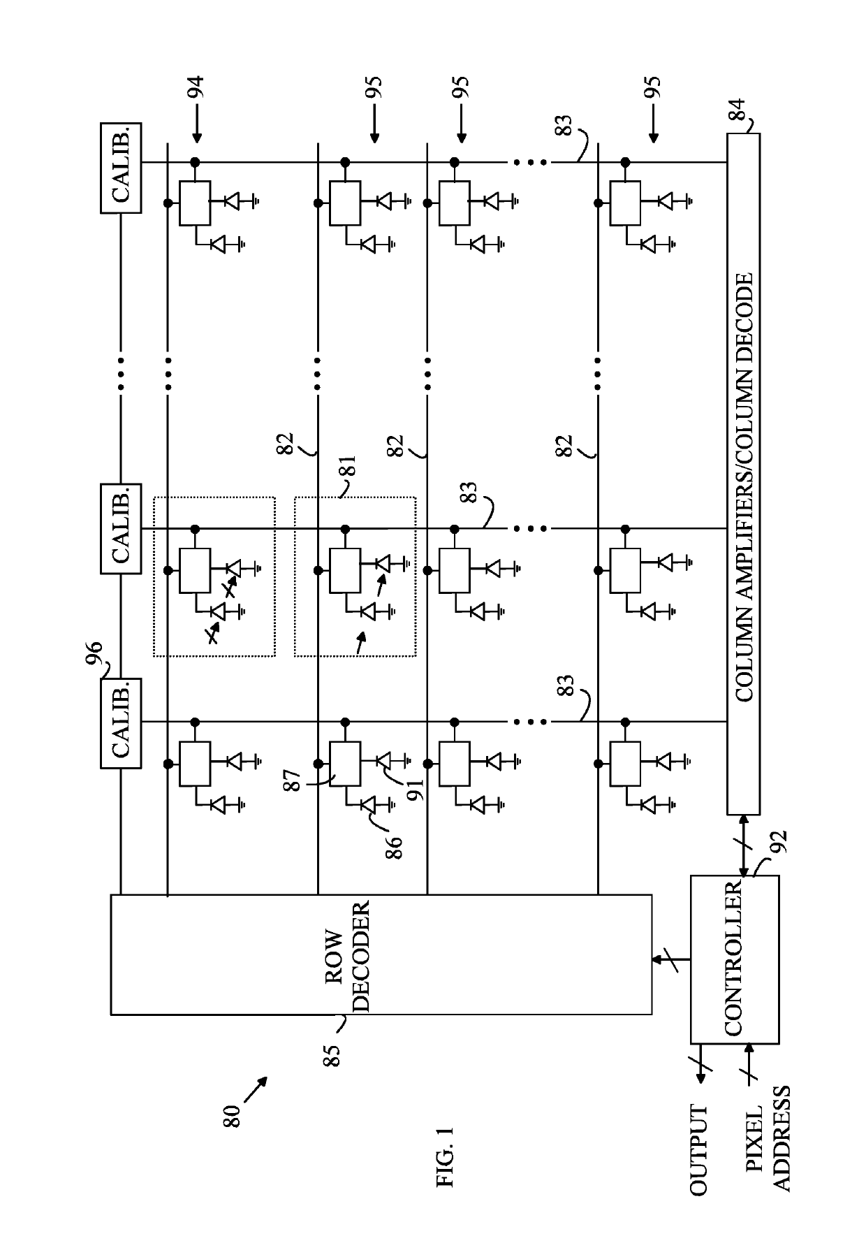
[0025]To simplify the following discussion, a pixel sensor is defined to be a circuit that converts light incident thereon to an electrical signal having a magnitude that is determined by the amount of light that was incident on that circuit in a period of time, referred to as the exposure. The pixel sensor has a gate that couples that electrical signal to a readout line in response to a signal on a row select line.

[0026]A rectangular imaging array is defined to be a plurality of pixel sensors organized as a plurality of rows and columns of pixel sensors. The rectangular array includes a plurality of readout lines and a plurality of row select lines, each pixel sensor being connected to one row select line and one readout line, the electrical signal generated by that pixel being connected to the readout line associated with that pixel in response to a signal on the row select line associated with that pixel sensor.

[0027]The manner in which the present invention provides its advantag...


PUM


Abstract

An apparatus for taking moving pictures, a method for taking moving pictures, and a novel pixel sensor array are disclosed. The apparatus includes a rectangular imaging array, a plurality of column processing circuits, and a controller. The rectangular imaging array is characterized by a plurality of rows and columns of UHDR pixel sensors and a plurality of readout lines, and a plurality of row select lines. Each column processing circuit is connected to a corresponding one of the plurality of readout lines. The controller causes the rectangular imaging array to measure a plurality of images of a scene that is illuminated by a pulsating light source characterized by an illumination period and a dark period. Each of the images is generated in a frame period which includes an exposure period and a dead period, the dead period being less than the dark period.

Description

BACKGROUND OF THE INVENTION[0001]The power efficiency, high brightness, and long lifetime have made LEDs the lighting source of choice in many applications including street lighting, stoplights, car headlights, car brake lights, road signage, store signage, etc. The typical method for setting the light intensity from the LEDs is to drive the LEDs with a constant current and modulate the fraction of the time during which the LED is on. This is referred to as a Pulse Width Modulation (PWM) driver scheme. This scheme allows the LED to operate at the optimal driving current and deliver the desired brightness with low power consumption. The pulsing also helps keep the operating temperature low and extends the LED life. Each manufacturer and each application tends to arrive at a different optimal frequency and duty cycle.[0002]While the pulsating nature of the illumination is not a problem for the human eye, which cannot detect pulses at the frequencies used to control the LEDs, the pulse...

Claims


Application Information

Patent Timeline
30 May 2019
Publication
US20190166291A1
IPC
H04N5/235; H04N5/355; G06T5/00; H04N9/68
CPC
H04N5/235; H04N5/355; G06T5/007; H04N9/68; H04N23/74; H04N25/623; H04N25/677; H04N25/532
Inventors
MAGNANI, ALBERTO M.; ADAMS, CHRISTOPHER R.