
System and method for determining temperature nadir of a female

a technology of electronic system and temperature nadir, which is applied in the field of electronic system and a method for determining the temperature nadir during the menstrual cycle of the female human, can solve the problems of cumbersome and unreliable use of non-hormonal birth control tools, such as these apps or the well-known temperature method, by many women, and neither the classical temperature method nor the symptothermal method allow precise detection of ovulation in real-tim

Active Publication Date: 2019-06-06
AVA SCI-FMTC LLC +1
View PDF2 Cites 11 Cited by
  • Summary
  • Abstract
  • Description
  • Claims
  • Application Information

AI Technical Summary

Benefits of technology

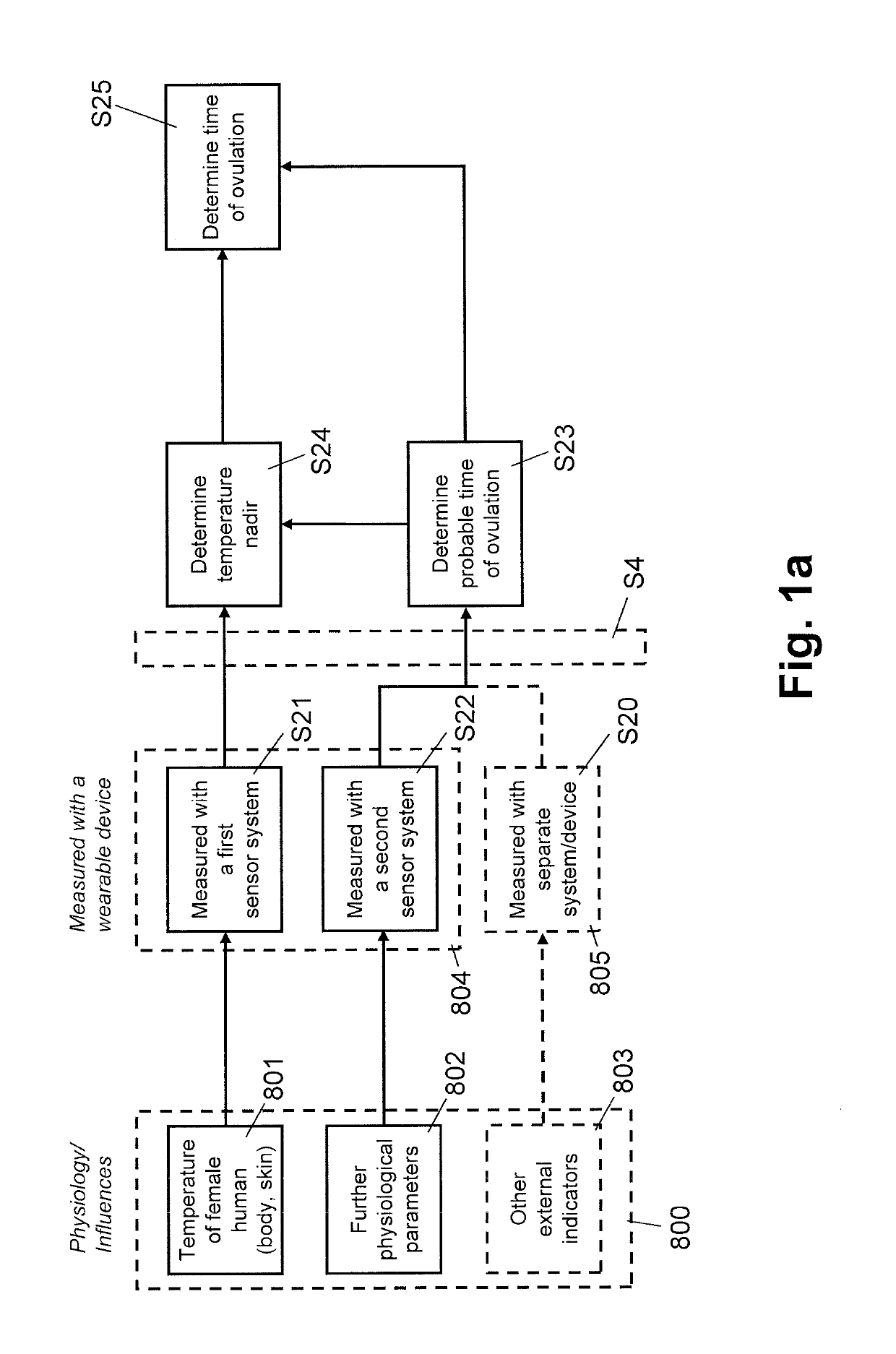
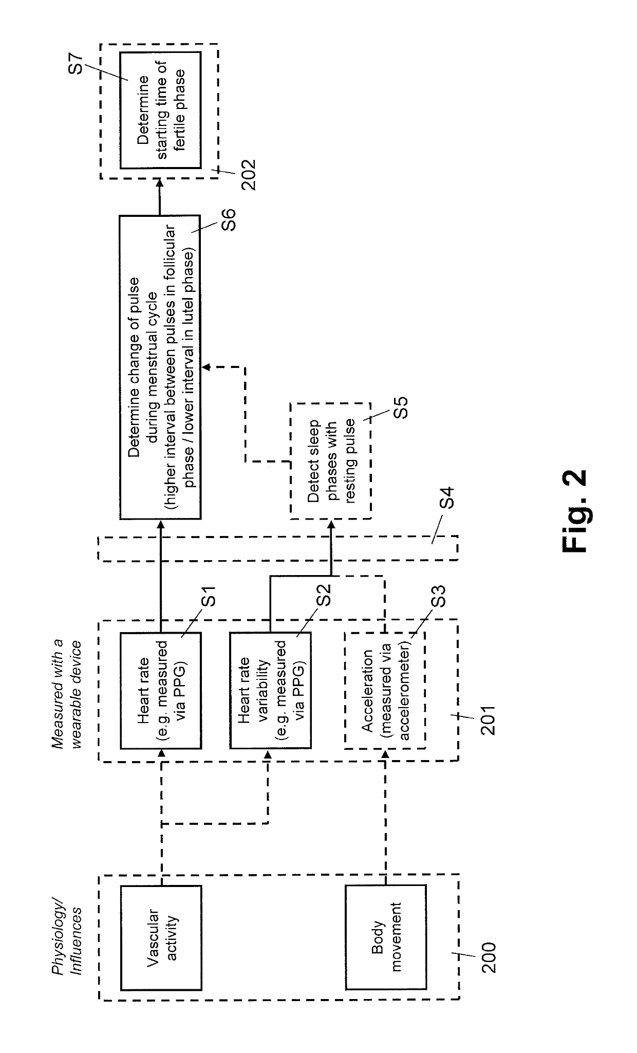
This patent describes an electronic system and method for detecting the time of ovulation and peak oestrogen level in a female human by measuring the temperature of the person. The system uses data from a wearable device and other external sensors to determine the starting point of the fertility phase and the temporary decrease in temperature that occurs around that time. By detecting the temperature nadir, the system is able to accurately identify the time of ovulation and peak oestrogen level. This invention provides a non-invasive and real-time way to determine the time of sure ovulation and peak oestrogen level, which can help with fertility planning and treatment.

Problems solved by technology

Nevertheless, most non-hormonal birth control tools, such as these apps or the well-known temperature method, are found cumbersome and unreliable by many women.
While this yields a better reliability, it is typically found complicated and very cumbersome by women.
But s neither the classical temperature method nor the symptothermal method allow precise detection of ovulation in real-time.
0.1 C in the signal, and that signal noise from confounding parameters are in the same range, it is hardly possible to identify the correct temperature nadir.

Method used


Image

  • System and method for determining temperature nadir of a female
  • System and method for determining temperature nadir of a female
  • System and method for determining temperature nadir of a female

Examples


Embodiment Construction

s

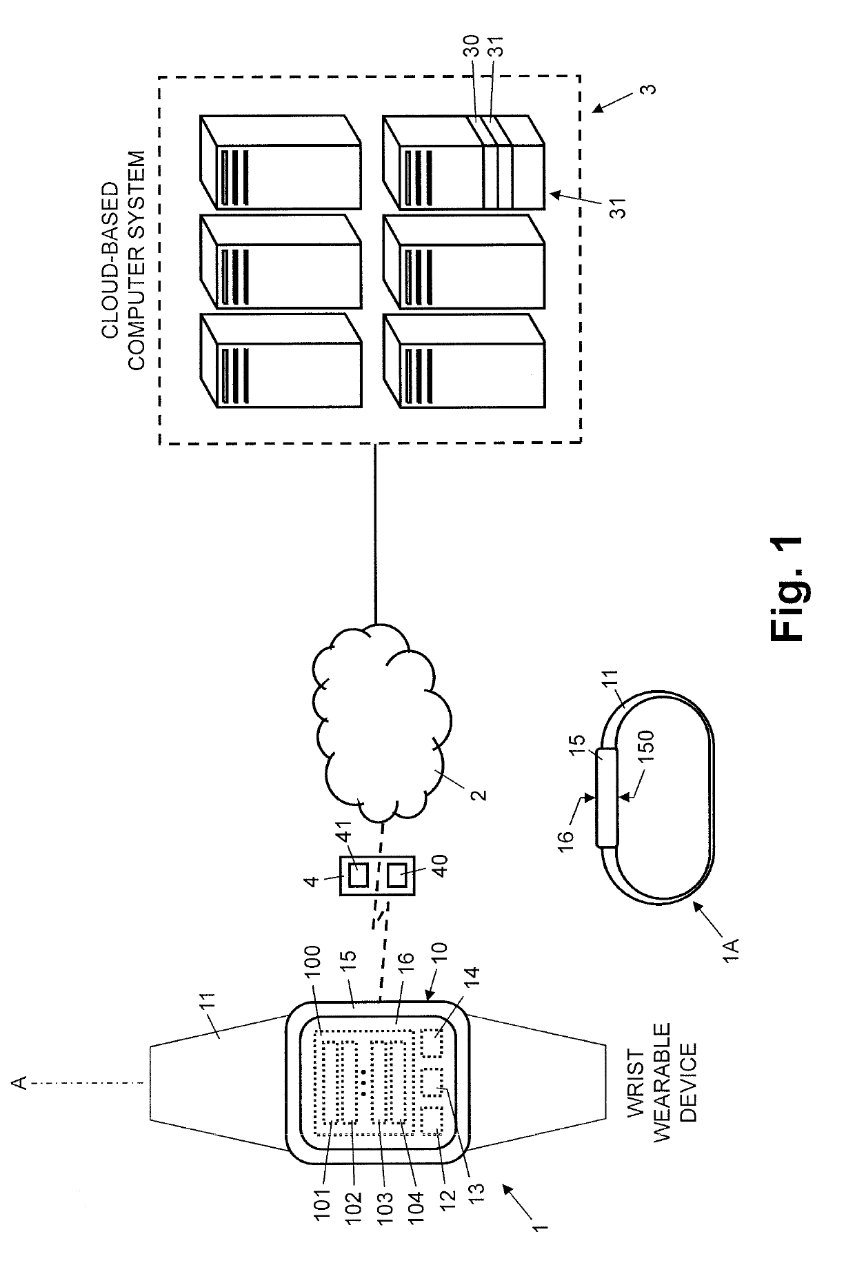
[0040]In FIG. 1, reference numeral 3 refers to a computer system, e.g. a cloud-based computer system, comprising one or more computers 31 with one or more processors 30 and a data storage system 31. The computer system 3 or its processors 30, respectively, are connected to the data storage system 31 and configured to execute various functions, as will be explained later in more detail. The data storage system 31 comprises RAM, flash memory, hard disks, data memory, and / or other data stores.

[0041]In FIG. 1, reference numeral 4 refers to a mobile communication device, e.g. a cellular telephone or a tablet computer, comprising one or more processors 40 and a data store 41. The processors 40 are connected to the data store and configured to execute various functions, as will be explained later in more detail. The data store comprises RAM, flash memory, data memory, and / or other data storage systems.

[0042]In FIG. 1, reference numeral 1 refers to a wearable device, e.g. a wrist wearable ...


PUM


Abstract

An electronic system for determining a time of the temperature nadir of a female human during the menstrual cycle comprises a wearable device (1) that includes a first sensor system (104), configured to determine a temperature of the female human, and a second sensor system (101, 102, 103), configured to determine one or more further physiological parameters of the female human. The electronic system further comprises a processor (13, 30, 40), configured to determine a detected starting point of the fertility phase of the female human, using the one or more further physiological parameters of the female human. The processor (13, 30, 40) is further configured to detect the temperature nadir as a temporary decrease in the temperature, using the detected starting point of the fertility phase of the female human. The time of the temperature nadir is used as an indicator of the time of ovulation and peak oestrogen level.

Description

FIELD OF THE INVENTION[0001]The present invention relates to an electronic system and a method for determining a temperature nadir during a menstrual cycle of a female human. Specifically, the present invention relates to an electronic system and a method for determining a temperature nadir during a menstrual cycle of a female human using a wearable device with sensor systems for measuring physiological parameters.BACKGROUND OF THE INVENTION[0002]Since the introduction of the contraceptive pill in 1960, decades have passed without major developments in the birth control market. In the recent years, so called fertility apps for mobile devices were becoming attractive for an increasing number of women. These applications use the calendar method for determining fertile time periods. Nevertheless, most non-hormonal birth control tools, such as these apps or the well-known temperature method, are found cumbersome and unreliable by many women. Generally, by relying on more than one physio...

Claims


Application Information

Patent Timeline
Patent Type & Authority Applications(United States)
IPC IPC(8): A61B10/00A61B5/0205A61B5/01
CPCA61B10/0012A61B5/02055A61B5/01A61B5/02438A61B5/0533A61B2010/0019A61B2010/0029A61B5/4306A61B2010/0016
Inventor STEIN, PETERLEENERS, BRIGITTE
Owner AVA SCI-FMTC LLC
Learn More