In-line swirl vortex separator

a separator and swirl technology, applied in the direction of vortex flow apparatus, dispersed particle separation, single direction vortex, etc., can solve the problems of increasing the difficulty of difficult separation of particles from gas streams containing medium size solid particles (100 microns) and particularly small size solid particles (1 microns)

Active Publication Date: 2019-06-06
BRATTON RODNEY ALLAN
View PDF0 Cites 2 Cited by
  • Summary
  • Abstract
  • Description
  • Claims
  • Application Information

AI Technical Summary

Benefits of technology

[0031]In one embodiment, the angle, position, height and length of the vortex tabs are matched to a gas flow rate within the flow conduit to effect separation of solid particles smaller than 1 micron from the flowing gas.

Problems solved by technology

Generally, as discussed below, as particles become smaller, it is increasingly difficult to separate them from a gas stream.
In particular, gas streams containing medium size solid particles (<100 microns) and particularly small size solid particles, (<1 microns) are difficult to separate from a gas stream due to their low mass, low settling velocities and susceptibility to turbulence.
These particles fall slowly and may take days to years to settle out of a quiet atmosphere.
In a turbulent atmosphere they may never settle out but can be washed out by water or rain.
As noted, the difficulty in separating smaller particles is a result of their small mass and low settling velocities.
This problem is compounded by any turbulence of the gas media they, may be within.

Method used


Image

  • In-line swirl vortex separator
  • In-line swirl vortex separator
  • In-line swirl vortex separator

Examples


example 1

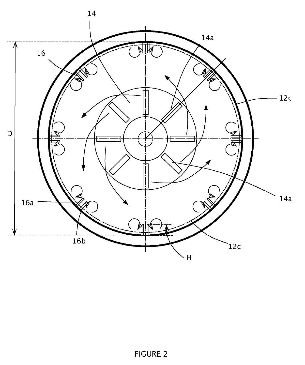
[0072]A system comprising a horizontal clear tube having a 6 inch internal diameter and 4.5 foot length was tested with a 700 ACFM (actual cubic feet per minute) air flow. The system included swirl element vanes oriented at 50 degrees to the flow path together with 4 pairs of vortex tabs spaced evenly about the inner housing. Each pair of vortex vanes had straight leading and trailing edges and had a height of 0.4 inches and a length of 2.3 inches. For testing purposes, fine threads were attached to the inner trailing edge corner to visually observe the creation and direction of flow of vortices off the trailing edges. The vortex vanes of a pair were separated by 0.5 inches and angled at approximately 50 degrees to the longitudinal axis of the housing.

[0073]For a given vortex tab orientation, air flow was established and the movement of tell tales observed. As airflow was steadily increased from 0 to 700 ACFM, the telltales would initially show no discernable pattern of movement. As...

example 2

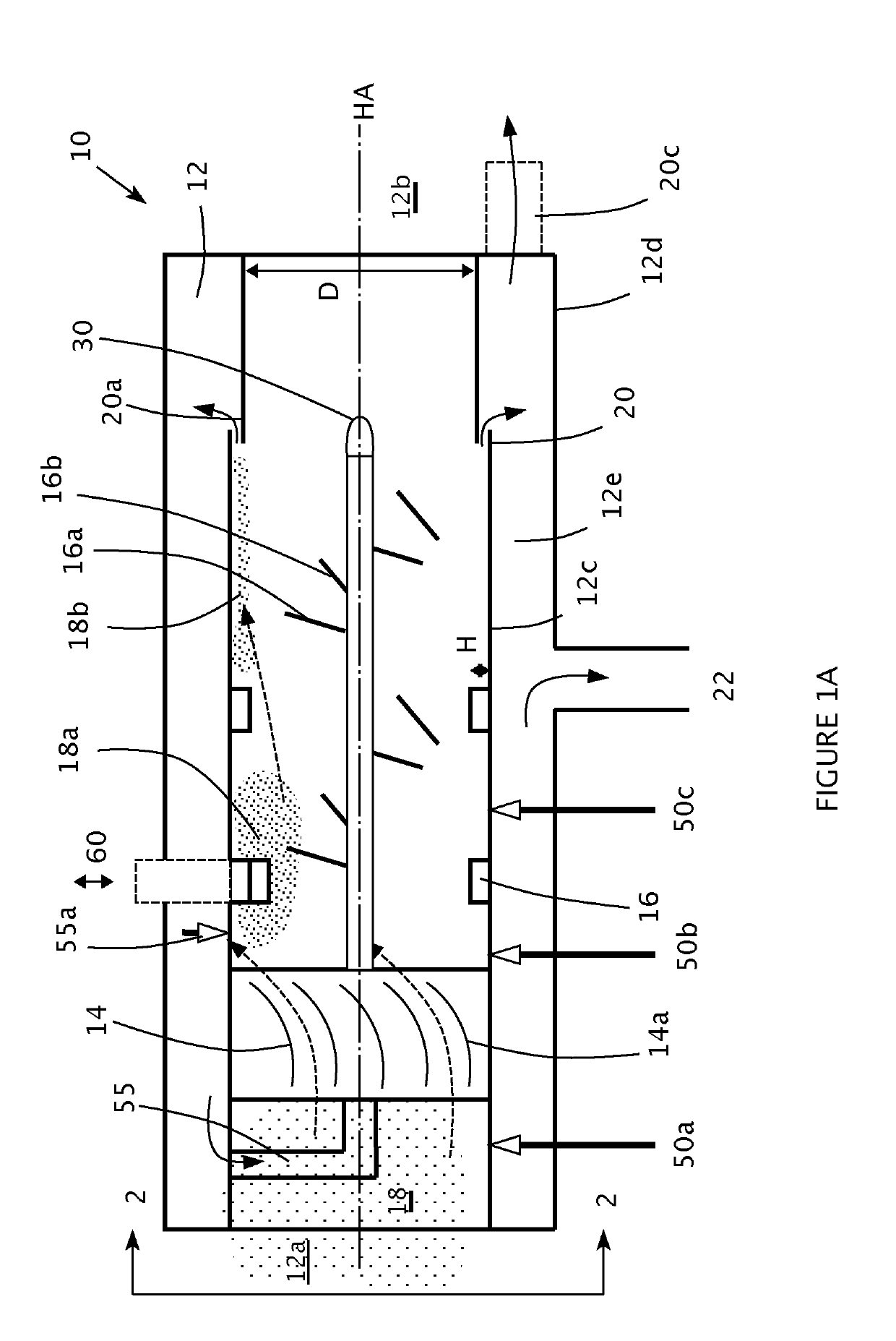
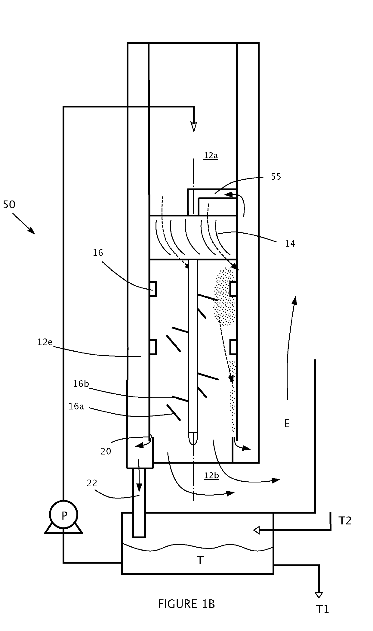
[0077]A vertical clear tube housing with a 4 inch outside diameter and an inside diameter of 3.75 inches was set with a swirl element that induced a swirl at 58 degrees to the longitudinal axis. An inside tube having an OD of 1.32 inches ran the length of the tube in the centre.

[0078]Water was injected above the swirl element through 6 holes having 0.08 inch diameter and evenly spaced about the tube housing. The flow rate of the water was maintained at approximately 6 gallons per hour.

[0079]Air flow through the housing was maintained at 100 ACFM (actual cubic feet per minute). Talcum powder having a mean particle size diameter less of 0.5 microns was introduced to the air flow via a 100 psi air injection system upstream of the swirl element at right angles to the direction of air flow through the housing. With the rate of injection and angles of intersection, the powder was observed as being fully dispersed within the air flow almost instantaneously.

[0080]A bank of Filterite™ sub mi...


PUM

PropertyMeasurementUnit
angleaaaaaaaaaa
lengthaaaaaaaaaa
sizeaaaaaaaaaa

Abstract

An in-line swirl vortex separator to separate solids, liquids, particulate from a vapor stream. The swirl vortex separator includes a swirl element and a vortex element. The vortex element creates pairs of vortices that are substantially equal and opposite in direction.

Description

FIELD OF THE INVENTION[0001]The present disclosure relates generally to systems and methods for removing non-gaseous materials from a vapor stream. More particularly, the present disclosure relates to removing small and small / medium solid particles and fine liquid drops from a flowing vapor stream.BACKGROUND OF THE INVENTION[0002]Flowing vapor (i.e. gas) streams may contain undesirable particles or droplets of material, for example liquid droplets and solid particles. In many applications, it is desirable to separate these undesirable droplets / particles from the gas stream. Generally, as discussed below, as particles become smaller, it is increasingly difficult to separate them from a gas stream.[0003]In particular, gas streams containing medium size solid particles (<100 microns) and particularly small size solid particles, (<1 microns) are difficult to separate from a gas stream due to their low mass, low settling velocities and susceptibility to turbulence.[0004]For the pur...

Claims


Application Information

Patent Timeline
Patent Type & Authority Applications(United States)
IPC IPC(8): B01D45/12
CPCB01D45/12B01D45/16B04C3/00B04C3/06B04C5/103B04C2003/006
Inventor BRATTON, RODNEY ALLAN
Owner BRATTON RODNEY ALLAN
Why Eureka
Try Eureka