Power tool

a technology of power tools and housing structures, applied in the field of power tools, can solve the problems that the housing structure of power tools does not necessarily have, and achieve the effects of improving the workability of the power tool in dark places, stably holding the switching member, and enhancing the flexibility of the design of the grip parts

Active Publication Date: 2019-06-06
MAKITA CORP
View PDF29 Cites 8 Cited by
  • Summary
  • Abstract
  • Description
  • Claims
  • Application Information

AI Technical Summary

Benefits of technology

[0012]The power tool according to the present aspect is of the type that the user can operate the operation part disposed in the first end part, in which the spindle is also disposed, while holding the grip part. According to the present aspect, the switch is disposed in the second end part, so that flexibility in designs of the grip part can be enhanced. With this structure, the switching member needs to have a length at least corresponding to the grip part, but at least a portion of the holding member extending within the grip part can stably hold the switching member.
[0013]In one aspect of the present disclosure, the power tool may further include an illumination device and a wiring for power supply. The illumination device may be disposed in the first end part and configured to illuminate a working region of the tool accessory. The wiring may extend from the second end part and may connect to the illumination device. The holding member may be configured to guide the wiring from the second end part to the first end part. In other words, the holding member may also serve as a guide member for guiding the wiring for the illumination device, as well as holding the switching member of the switch. According to the present aspect, workability of the power tool in dark places can be improved by the illumination device. Further, a rational structure of guiding the wiring from the second end part to the illumination device disposed in the first end part can be realized, by effectively utilizing the holding m...

Problems solved by technology

However, power tools do not nece...

Method used


Image

  • Power tool
  • Power tool
  • Power tool

Examples


first embodiment

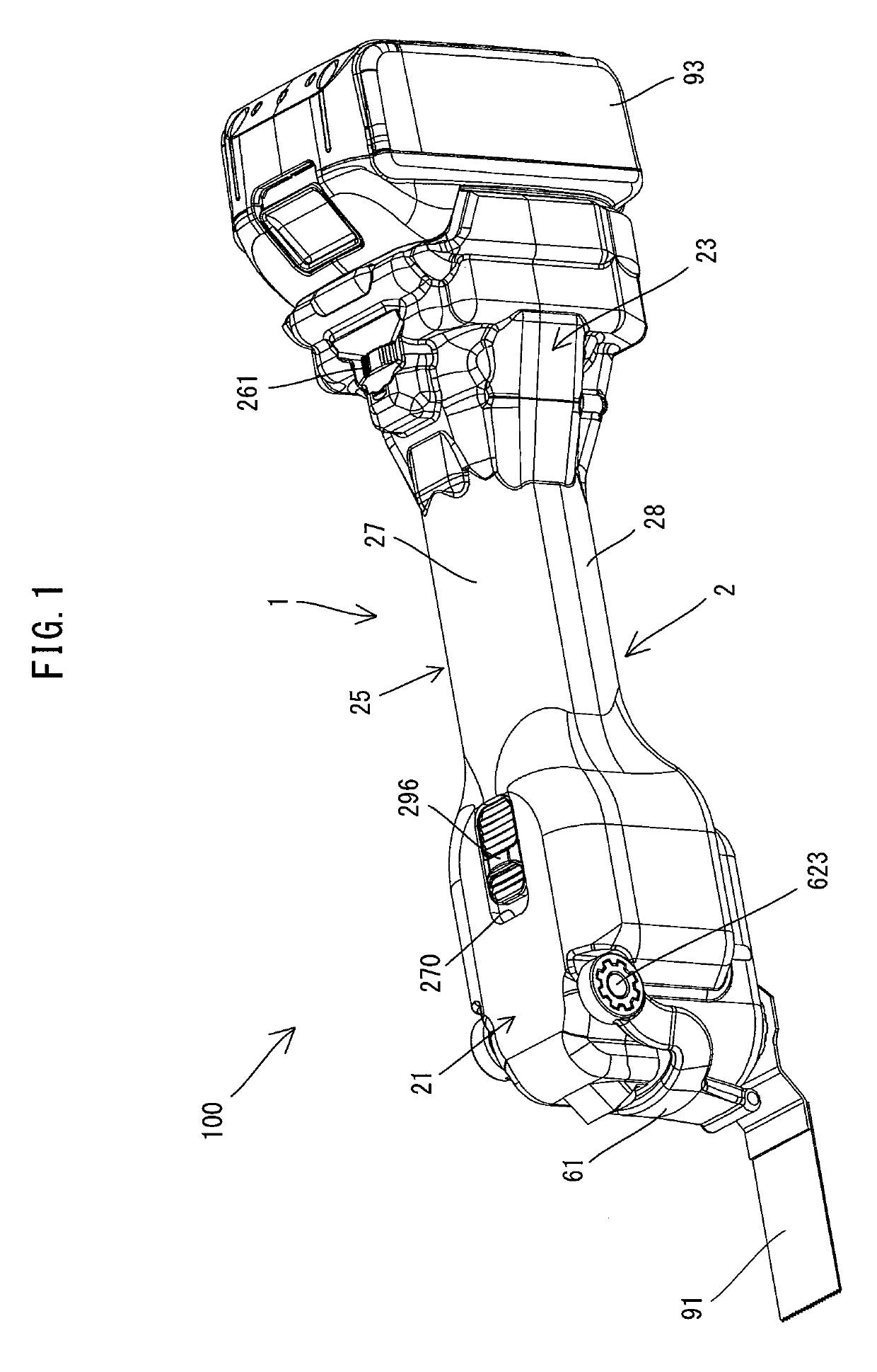
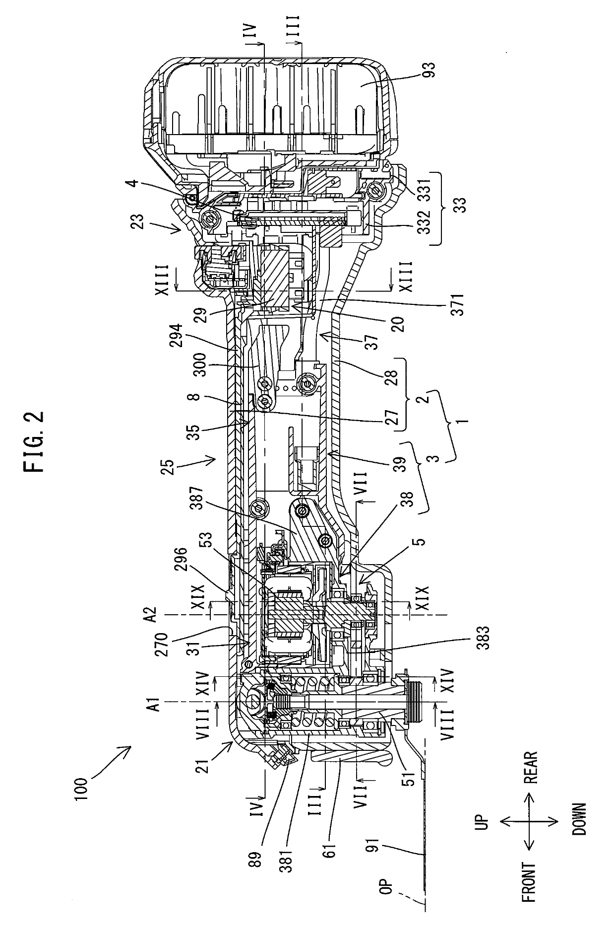
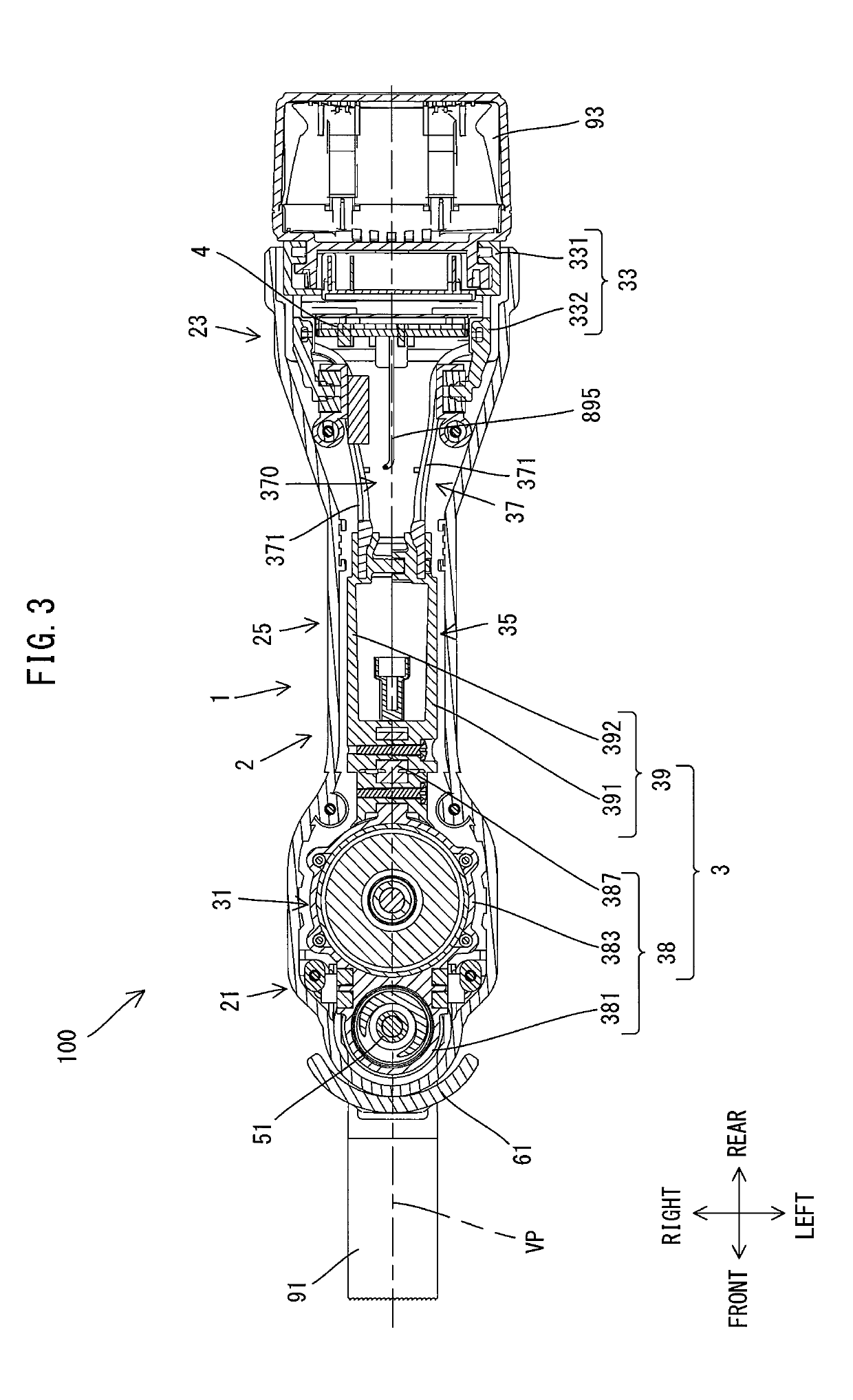
[0045]A first embodiment is now explained with reference to FIGS. 1 to 22. In the present embodiment, an electric oscillating tool 100 is described as an example which performs a processing operation on a workpiece (not shown) by oscillatory driving a tool accessory 91 (see FIG. 1). Plural kinds of tool accessories 91 such as a blade, a scraper, a grinding pad and a polishing pad which can be mounted to the oscillating tool 100 are available for the oscillating tool 100. In order to perform a desired operation such as cutting, scraping, grinding and polishing, a user may select one of the tool accessories 91 which is suitable for the desired operation and mount the tool accessory 91 to the oscillating tool 100. In the drawings referenced below, a blade mounted to the oscillating tool 100 is shown as an example of the tool accessory 91.

[0046]First, the general structure of the oscillating tool 100 is explained. As shown in FIGS. 1 and 2, the oscillating tool 100 includes an elongate ...

second embodiment

[0121]An oscillating tool 101 according to a second embodiment is now described with reference to FIG. 23. Like the oscillating tool 100 of the first embodiment, the oscillating tool 101 of the present embodiment is also configured to reciprocally rotate the spindle 51 within a specified angle range around the axis A1 by power of the motor 53 configured as a brushless DC motor. The power source of the oscillating tool 101 is, however, an external AC power source (commercial power supply), in place of the battery 93 mounted to the battery-mounting part 331. Therefore, a rear-end part 330 of an inner housing 30 of the oscillating tool 101 and its internal configuration are different from the rear-end part 33 and its internal configuration of the first embodiment. The other structures of the oscillating tool 101 are otherwise substantially identical to those of the oscillating tool 100 of the first embodiment. Therefore, the structures which are substantially identical to those in the ...


PUM

PropertyMeasurementUnit
Angleaaaaaaaaaa
Poweraaaaaaaaaa
Distanceaaaaaaaaaa

Abstract

A power tool includes a motor, a switch, a housing, a switching member and a holding member. The housing is a hollow body formed by a first housing part and a second housing part connected with the first housing part. The first housing part has a through hole. The switching member is connected to the switch and includes an operation part exposed outside through the through hole so as to be movable in a specified direction in response to a user's manual operation. The switching member is configured to turn the switch on and off by linearly moving in the specified direction. The holding member is supported by at least one of the first housing part and the second housing part within the housing and configured to hold the switching member between the holding member and the first housing part so as to be linearly movable in the specified direction.

Description

CROSS-REFERENCE TO RELATED APPLICATION[0001]The present application claims priorities to Japanese patent application No. 2017-232069 filed on Dec. 1, 2017, and Japanese patent application No. 2017-232070 filed on Dec. 1, 2017. The contents of the foregoing applications are fully incorporated herein by reference.TECHNICAL FIELD[0002]The present disclosure relates to a power tool, and more specifically, to a power tool which is configured to turn a switch on and off via a slidable operation part.BACKGROUND ART[0003]A power tool which is configured to drive a tool accessory has an operation part which can be operated to switch on and off a switch for driving and stopping a motor. For example, Japanese laid-open patent publication No. 2017-80827 discloses a power tool which is configured to oscillatory drive a tool accessory mounted to a spindle, using a motor as a driving source. In this power tool, a switch for driving and stopping the motor is turned on and off by a sliding movement ...

Claims


Application Information

Patent Timeline
IPC IPC(8): B25F5/00B25F3/00
CPCB25F5/006B25F3/00B23D61/006B24B23/04B24B47/12B27B19/006B23D51/01B25F5/02
Inventor AOKI, YONOSUKE
Owner MAKITA CORP
Why Eureka
Try Eureka