
Bypass conduits for reducing thermal fatigue and stress in heat recovery steam generators of combined cycle power plant systems

Active Publication Date: 2019-06-06
GENERAL ELECTRIC CO
View PDF4 Cites 1 Cited by
  • Summary
  • Abstract
  • Description
  • Claims
  • Application Information

AI Technical Summary

Benefits of technology

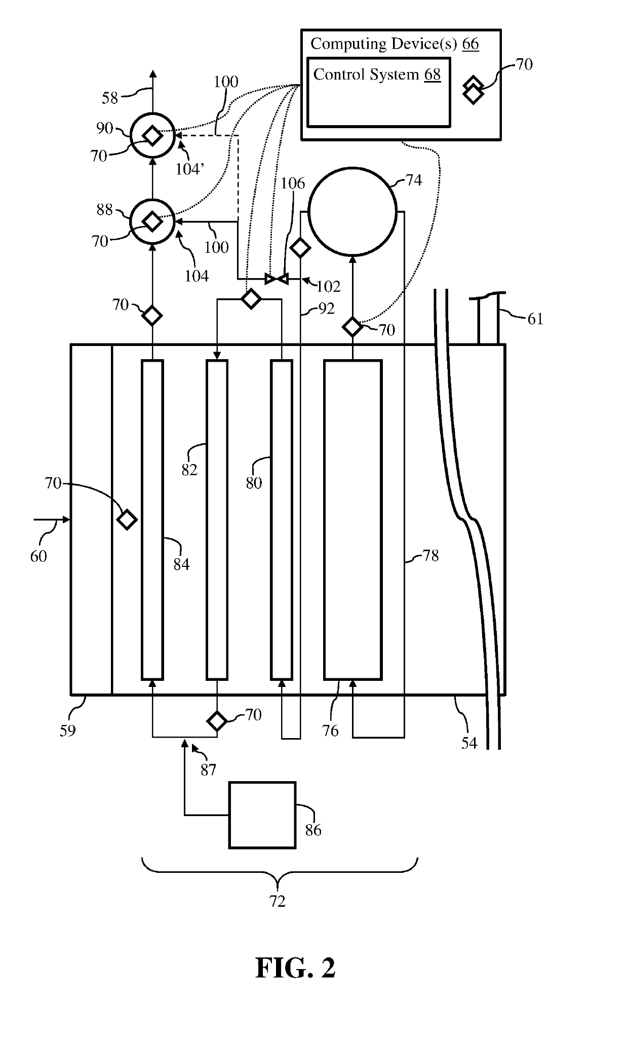
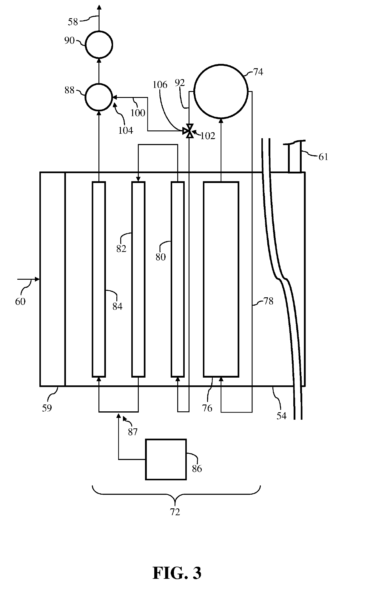
The patent text describes a heat recovery steam generator (HRSG) for a combined cycle power plant system. The HRSG includes a steam generator module that produces steam, two superheater modules, and a bypass conduit. The bypass conduit receives a portion of the steam generated by the steam generator module and includes a valve to provide the steam to the outlet of the conduit. The system also includes a gas turbine system that produces exhaust gas, and the HRSG is in fluid communication with the turbine system for receiving the exhaust gas. The technical effects of the patent text include improved system efficiency and reduced emissions.

Problems solved by technology

However, during operation of the power system, portions and / or components may experience high stress and thermal fatigue due to rapid temperature change of the components.
The rapid temperature change may increase the high stress and / or thermal fatigue experienced by the components exposed to the high temperature steam during the start-up procedure.
Additionally, when the power plant is shut down again (e.g., not operational), the temperature of the components of the HRSG may again decrease to the pre-start temperature, and upon the next start-up procedure, may experience the same high stress and / or thermal fatigue.
In cases of continued exposure to high stress and / or thermal fatigue, components of the HRSG may degrade and / or become damaged, which may reduce operational performance of the power system.
Additionally, any damaged components may eventually need to be replaced, which requires the power system to be completely shut down while the damaged components are replaced.
The necessity to replace the damaged parts within the power system may reduce the operational time of the power system, which reduces the overall power or load output, and also increases the maintenance costs (e.g., component replacement) for the power system over the operational life of the system.

Method used


Image

  • Bypass conduits for reducing thermal fatigue and stress in heat recovery steam generators of combined cycle power plant systems
  • Bypass conduits for reducing thermal fatigue and stress in heat recovery steam generators of combined cycle power plant systems
  • Bypass conduits for reducing thermal fatigue and stress in heat recovery steam generators of combined cycle power plant systems

Examples


Embodiment Construction

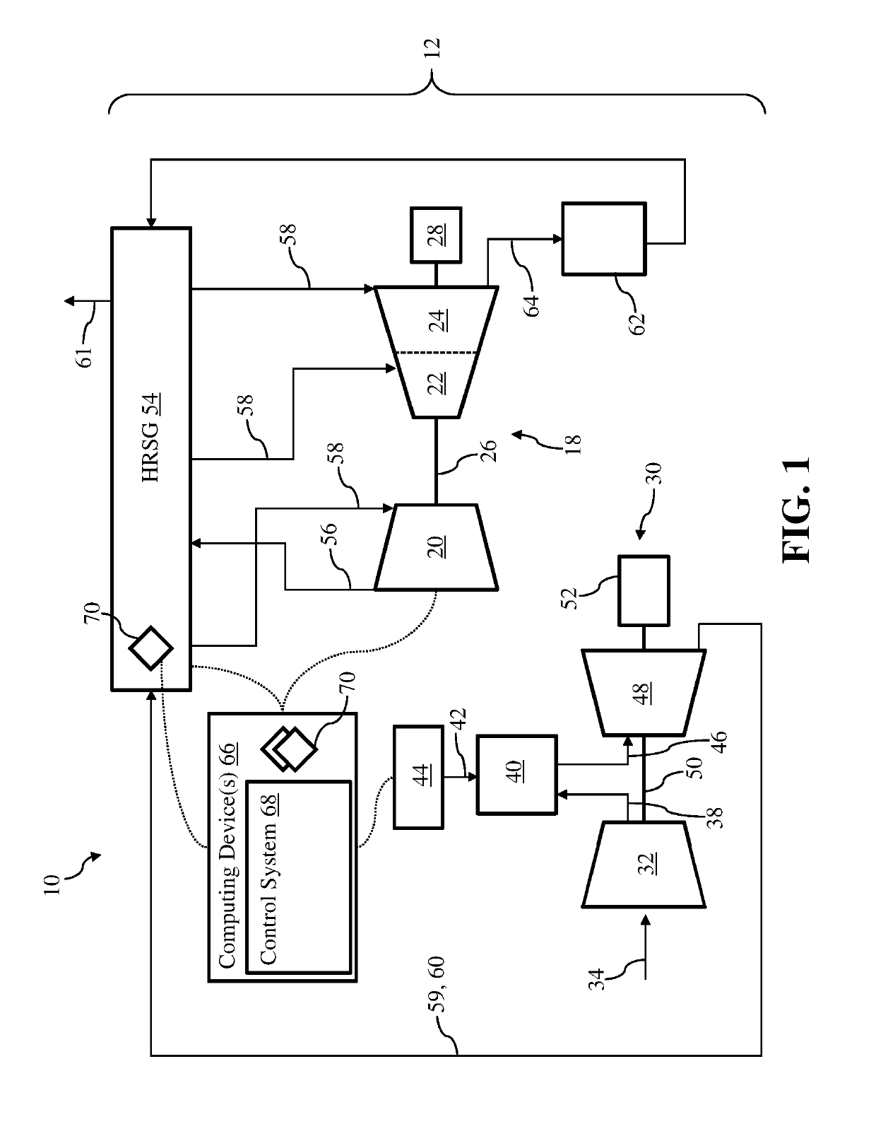
[0018]As an initial matter, in order to clearly describe the current disclosure it will become necessary to select certain terminology when referring to and describing relevant machine components within a combined cycle power plant system. When doing this, if possible, common industry terminology will be used and employed in a manner consistent with its accepted meaning. Unless otherwise stated, such terminology should be given a broad interpretation consistent with the context of the present application and the scope of the appended claims. Those of ordinary skill in the art will appreciate that often a particular component may be referred to using several different or overlapping terms. What may be described herein as being a single part may include and be referenced in another context as consisting of multiple components. Alternatively, what may be described herein as including multiple components may be referred to elsewhere as a single part.

[0019]In addition, several descriptiv...


PUM


Abstract

Heat recovery steam generators (HRSGs) including bypass conduits for reducing fatigue and / or stress experienced by components within the HRSGs are disclosed. The HRSG may include a steam generator module generating steam, and a first superheater module positioned downstream of the steam generator module. The first superheater module may receive the steam generated by the steam generator module. The HRSG may also include a second superheater module positioned downstream from the first superheater module, and a bypass conduit for receiving a portion of the steam generated by the steam generator module. The bypass conduit may include an inlet positioned downstream of the steam generator module, and an outlet positioned downstream of the first superheater module. Additionally, the HRSG may include a valve in fluid communication with the bypass conduit to provide steam to the outlet of the bypass conduit.

Description

BACKGROUND OF THE INVENTION[0001]The disclosure relates generally to combined cycle power plant system, and more particularly, to bypass conduits for reducing fatigue and stress experienced by components within a heat recovery steam generator (HRSG) of the combined cycle power plant system.[0002]Power systems typically include a variety of different turbomachines and / or systems that are used to generate operational load and / or power output. Two conventional power systems used to generate operational loads include gas turbine systems and combined cycle power plants, which typically include a gas turbine system(s). Conventional combined cycle power plants employ one or multiple gas turbine system(s) operatively coupled to one or multiple steam turbine system(s). The gas turbine system includes a compressor coupled to a gas turbine. The gas turbine is usually coupled to and drives an external component, such as a generator, for producing a load or power output. The steam turbine system...

Claims


Application Information

Patent Timeline
IPC IPC(8): F01K13/02F01K23/10F01K13/00
CPCF01K13/02F01K23/10F01K13/003Y02E20/16F22B1/1815F22G1/04F22B37/446
Inventor MAGEE, JEFFREY FREDERICKBRUNO, DENIS ROBERTDANG, VANDOUPIS, DIMITRIOS VASILIOSHERMAN, SCOTT WILLIAM
Owner GENERAL ELECTRIC CO
Learn More