Emission reduction system for use with a heat recovery steam generation system

a technology of heat recovery steam and emission reduction system, which is applied in the direction of emission prevention, separation process, and flue gas purification components, can solve the problems of catalyst temperature inconsistent with optimal performance level, high exhaust stream harmful emissions, and catalyst formation, etc., to reduce the size of the reactor, reduce the cost of the hrsg system, and reduce the amount of catalyst

Inactive Publication Date: 2009-11-19
JOHNSON MATTHEY INC
View PDF16 Cites 33 Cited by
  • Summary
  • Abstract
  • Description
  • Claims
  • Application Information

AI Technical Summary

Benefits of technology

[0033]The purpose of this patent is to achieve a narrow temperature zone to suit the catalyst's maximum performance window at all turbine/HRSG conditions. Additional benefit

Problems solved by technology

Combustion of fuel in a turbine and/or the duct burners inside the HRSG, lead to high temperatures in the exhaust stream with harmful emissions.
Also, the partial combustion of fuel inside the turbine and/or duct burners leads to formation of carbon monoxide (CO) and un-burnt hydrocarbons in addition to CO2 and water vapor.
However, this location of the catalyst typically has a temperature inconsistent with its optimal performance level.
Ammonia is a toxic gas.
This catalyst technology performs best in the temperature window of 650-750° F. If the temperature is below 650° F., the catalyst is under utilized, leading to excess NOx and ammonia emissions.
This application, however, does not address a method of removing the additional heat in the presence of duct firing.
While this appears to be an attractive solution, the temperature of the exhaust is so hot (around 1000° F.) which in turn impacts the longevity of such high temperature catalysts, forcing them to be replaced more frequently than catalyst placed in a lower temperature zone.
Also, the high temperature SCR catalysts are not hydrothermally stable.
This means that during operation of the turbine over this entire time period, the catalyst has to perform and meet emission requirements, which is difficult.
However, precious metal catalysts are expensive.
In addition, it is well known that pr

Method used


Image

  • Emission reduction system for use with a heat recovery steam generation system
  • Emission reduction system for use with a heat recovery steam generation system
  • Emission reduction system for use with a heat recovery steam generation system

Examples


example # 1

EXAMPLE #1

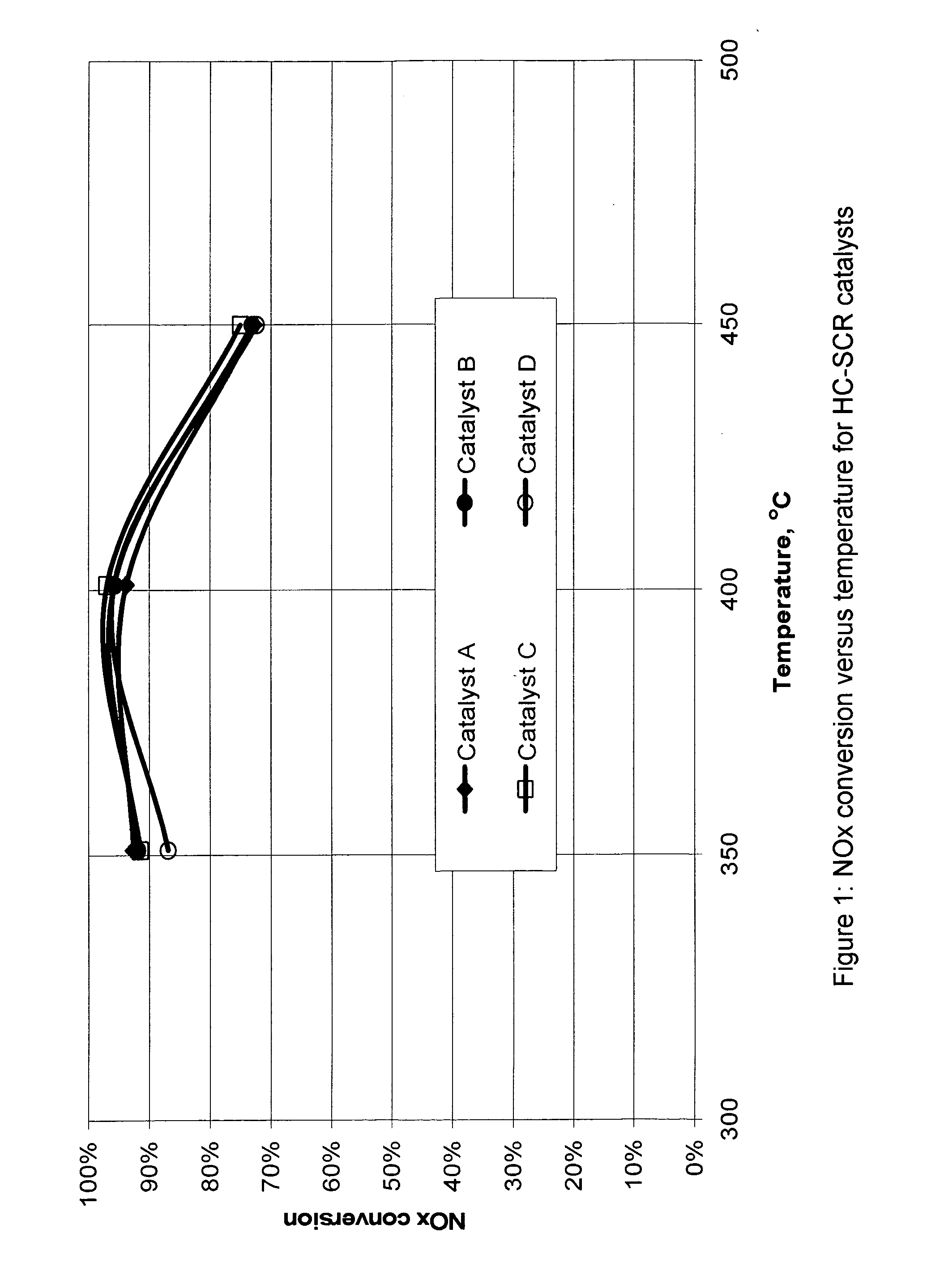
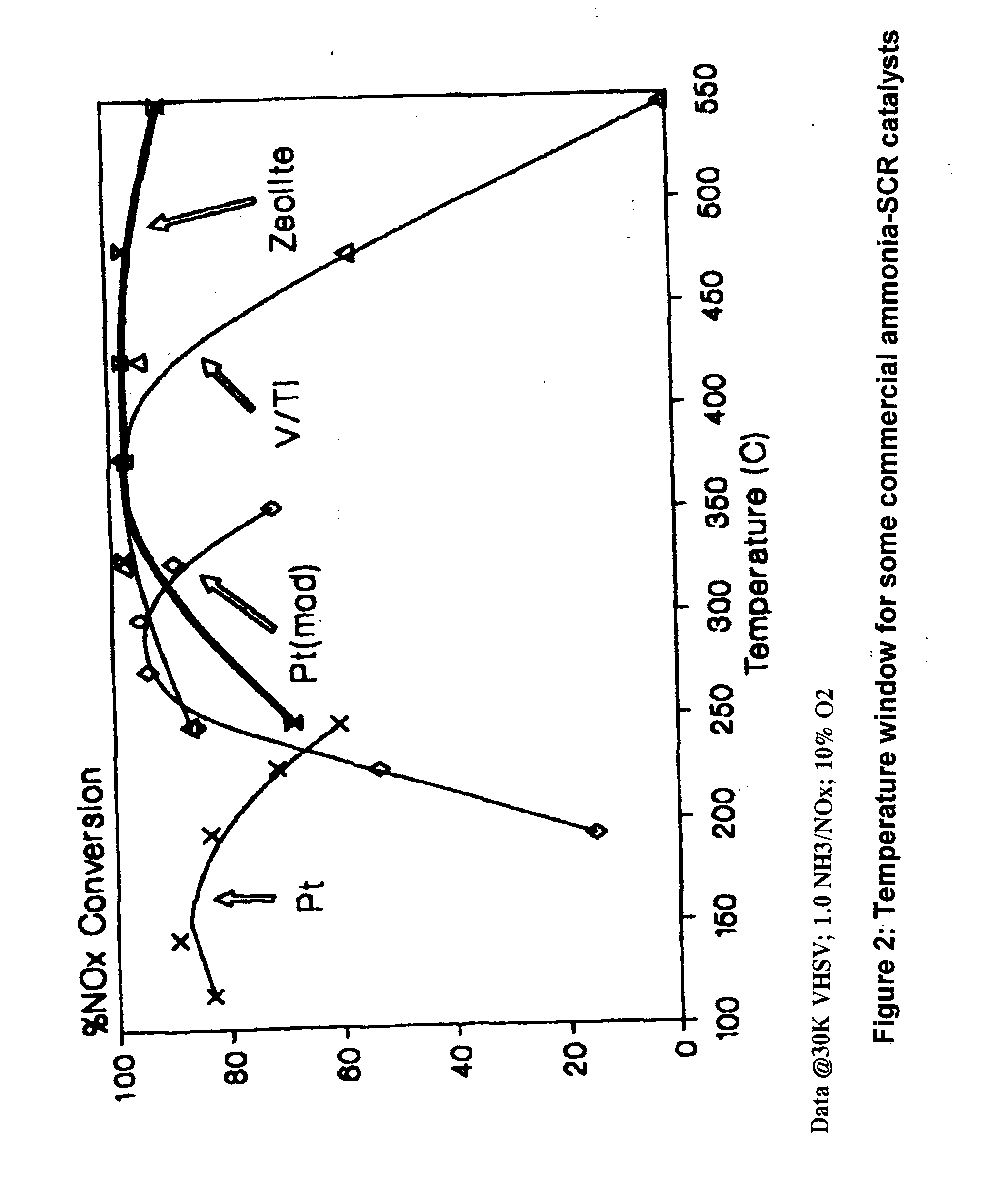
[0058]The temperature of exhaust stream entering the HRSG of a combined cycle combustion gas turbine can be about 600° F. to about 1100° F., more typically about 825° F. to about 1100° F. The amount of exhaust stream entering the HRSG varies considerably depending on the size of the combustion gas turbine used in the application and on varying operating conditions of a particular combustion gas turbine. Even though the amount of exhaust stream may vary, the temperature of this exhaust stream remains within the about 825° F. to about 1100° F. range. This exhaust stream temperature range, however, is too broad and not ideal for existing SCR catalyst technology, thus a much narrower temperature range is desired.

[0059]In a typical HRSG located downstream of a combustion gas turbine, saturated steam is produced in one or more heat exchange sections and sometimes superheated steam, or pre-heated air, or heat-transfer media, etc. are also heated by exchanging heat from the exhaus...

example # 2

EXAMPLE #2

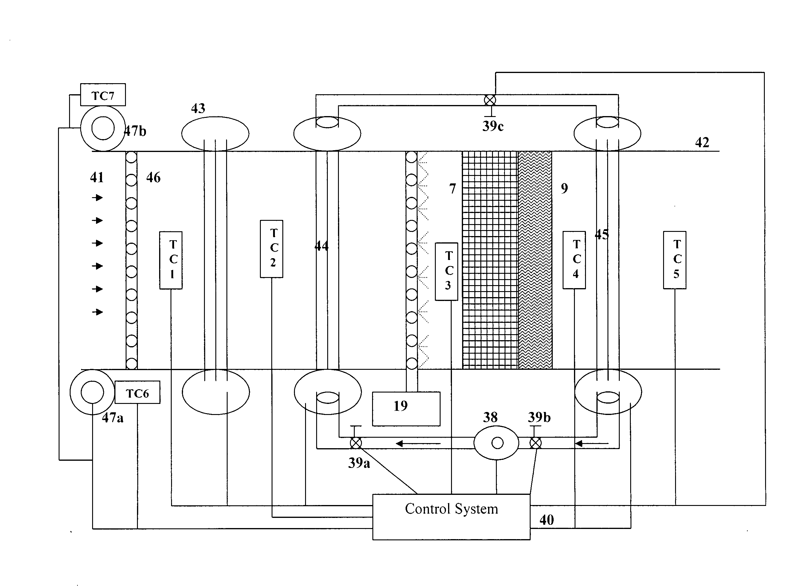
[0066]Basic components of the typical HRSG are shown in FIG. 4A. They are: Duct Firing Burners (31), Superheater Steam Bank (32), High Pressure Boiler Bank (33) Intermediate Pressure Boiler Bank (34), Low Pressure Boiler Bank (35), Economizer (36), and Air Preheater (37).

[0067]Under this invention, the basic HRSG components are arranged to consistently produce an exhaust stream temperature of around 765° F. plus or minus 50° F. at a particular location in the HRSG. Exhaust stream temperature may be raised (very rarely required) via duct burners, or lower (mostly required) via a heat exchange section.

[0068]An embodiment of the present invention produces a fixed exhaust downstream of any particular heat exchanger with the HRSG system. The use of a duct burner can generate excessive temperatures downstream of a particular heat exchanger (e.g. without limitation a tube bank), which can limit or reduce the effectiveness of pollution control catalyst systems. This invention addr...


PUM

PropertyMeasurementUnit
Temperatureaaaaaaaaaa
Fractionaaaaaaaaaa

Abstract

A system and method of maintaining an optimal temperature range for a catalyst section in a HRSG comprising placing a portion of the exhaust stream in a heat exchanger and superheater, diverting a second portion around the heat exchanger and superheater, combining the two portions and contacting the two portions with a catalyst section. Alternatively, a system of heat exchangers are employed to address the fluctuating exhaust temperature caused by the intermittent use of the duct burners.

Description

RELATED APPLICATIONS[0001]This application is a continuation-in-part of U.S. Provisional Application No. 61 / 127,708 filed May 15, 2008, which is herein incorporated by reference in its entirety.FIELD OF THE INVENTION[0002]This invention relates to a system and method for maintaining a workable temperature range for a catalyst system in a heat recovery steam generator (“HRSG”) system. These methods and systems are employed to reduce the NOx and CO emissions from the exhaust stream of a combined cycle gas turbine where in a waste heat boiler for recovering the steam (HRSG type) is used. The invention relates to means to provide the SCR catalyst the desired temperature window where it performs (preferably optimally), without sacrificing the HRSG efficiency.[0003]Gas turbines are used to generate electricity. Modern gas turbines are equipped with dual fuel capability and can run both on natural gas or other types of fuels such as diesel fuel, middle distillate, jet fuel etc.[0004]There ...

Claims


Application Information

Patent Timeline
IPC IPC(8): F01N3/20F02C7/00
CPCB01D53/343B01D53/8646B01D2251/2062F23J15/003F23J15/06F22B37/008F23J2219/10Y02E20/16Y02E20/363F22B1/1815F22B1/1861F23J2215/40Y02E20/30
Inventor BONO, ROBERTMALYALA, RAJASHEKHARAM V.MILLER, ALECGOLDEN, STEPHEN J.
Owner JOHNSON MATTHEY INC
Why Eureka
Try Eureka