Integrated solar-gas turbine cogeneration plant

a cogeneration plant and solar energy technology, applied in the field of power generation systems, can solve the problem that most cogeneration projects have a much shorter lead tim

Inactive Publication Date: 2012-05-31
KING FAHD UNIVERSITY OF PETROLEUM AND MINERALS
View PDF7 Cites 30 Cited by
  • Summary
  • Abstract
  • Description
  • Claims
  • Application Information

AI Technical Summary

Problems solved by technology

Furthermore, most cogeneration projects have a much shorter lead time than the large central generating stations.

Method used


Image

  • Integrated solar-gas turbine cogeneration plant
  • Integrated solar-gas turbine cogeneration plant

Examples


Embodiment Construction

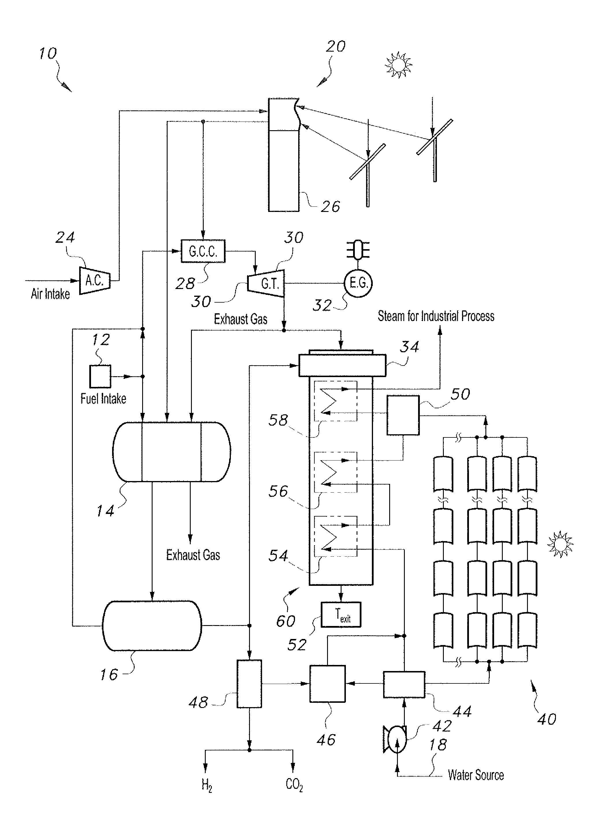
[0012]The integrated solar-gas turbine cogeneration plant, generally referred to in the drawings by the reference number 10 and hereinafter referred to as “ISGTCGP,” provides for more efficient production, operation, and economic operation of the ISGTCGP 10 by incorporating a fuel reformer 14 and solar energy sources for producing the necessary heat for the fuel reformer 14 and help steam production. Initially, it is noted that although valves are not explicitly mentioned, the description herein incorporates various valves and valve systems as is known in the art. In a production cycle, the ISGTCGP 10 utilizes solar energy to produce high quality fuel during sunlight availability via the fuel reformer 14 and utilizes the produced fuel during the periods of sunlight unavailability. Moreover, the processes involved in the fuel reformer 14 provide a means for utilizing captured carbon.

[0013]Referring to the drawing FIGURE, the ISGTCGP 10 uses methane as fuel, which is provided through ...


PUM


Abstract

The integrated solar-gas turbine cogeneration plant includes a fuel reformer, a plurality of solar collectors, and a gas turbine. The fuel reformer produces syngas to be used as fuel for the gas turbine. One solar collector is operatively connected to both the fuel reformer and the turbine to provide heat for the reforming reaction and to preheat air for a combustion chamber. Exhaust gas from the turbine is directed to the fuel reformer and to a heat recovery steam generator, the former as an additional heat source and the latter to heat the generator. Another solar collector is connected to the generator and heats a portion of the water being fed into the generator in order to help produce steam. The syngas is stored in a to fuel storage unit to provide fuel to the gas turbine continuously and to a supplemental heater on the steam generator during low insolation periods.

Description

BACKGROUND OF THE INVENTION[0001]1. Field of the Invention[0002]The present invention relates to power generation systems, and particularly to an integrated solar-gas turbine cogeneration plant that produces power efficiently and economically with minimal impact on the environment.[0003]2. Description of the Related Art[0004]Energy consumption and carbon dioxide emissions have become an increasing concern in the power and steam generation industry. A typical power plant using fossil fuels can produce tons of waste products such as carbon dioxide on an annual basis, even with strict regulation. Moreover, important factors, such as the balance between energy input and output for producing the power and the economics thereof, must be carefully considered and monitored in order to sustain a profitable and efficient power plant.[0005]Several different methods have been pursued in order to confront this problem. One solution lies in cogeneration. Cogeneration is the sequential production ...

Claims


Application Information

Patent Timeline
Patent Type & Authority Applications(United States)
IPC IPC(8): F02C3/28F02C7/08F02C6/14F03G6/04
CPCF02C1/05Y02E20/185F02C6/18F02C7/08C01B3/34C01B3/48F03G6/04F03G6/06C01B2203/0233C01B2203/0283C01B2203/043C01B2203/0475C01B2203/0811C01B2203/0827C01B2203/84C01B2203/86Y02E10/46Y02E20/14F02C6/14Y02P20/129Y02E20/18Y02P20/10Y02P20/133Y02P30/00F03G6/068
Inventor MOKHEIMER, ESMAIL M. A.HABIB, MOHAMED ABDEL-AZIZ
Owner KING FAHD UNIVERSITY OF PETROLEUM AND MINERALS
Why Eureka
Try Eureka