Ball bearing, spindle device, and machine tool
a technology of ball bearings and spindles, which is applied in the direction of roller bearings, engine components, mechanical equipment, etc., can solve the problems of increasing the cost of the spindle as a whole, increasing the labor of management, and increasing the labor of design/processing of the spindle, so as to achieve low speed, high initial preload, and good lubrication performance.
- Summary
- Abstract
- Description
- Claims
- Application Information
AI Technical Summary
Benefits of technology
Problems solved by technology
Method used
Image

Examples
first embodiment
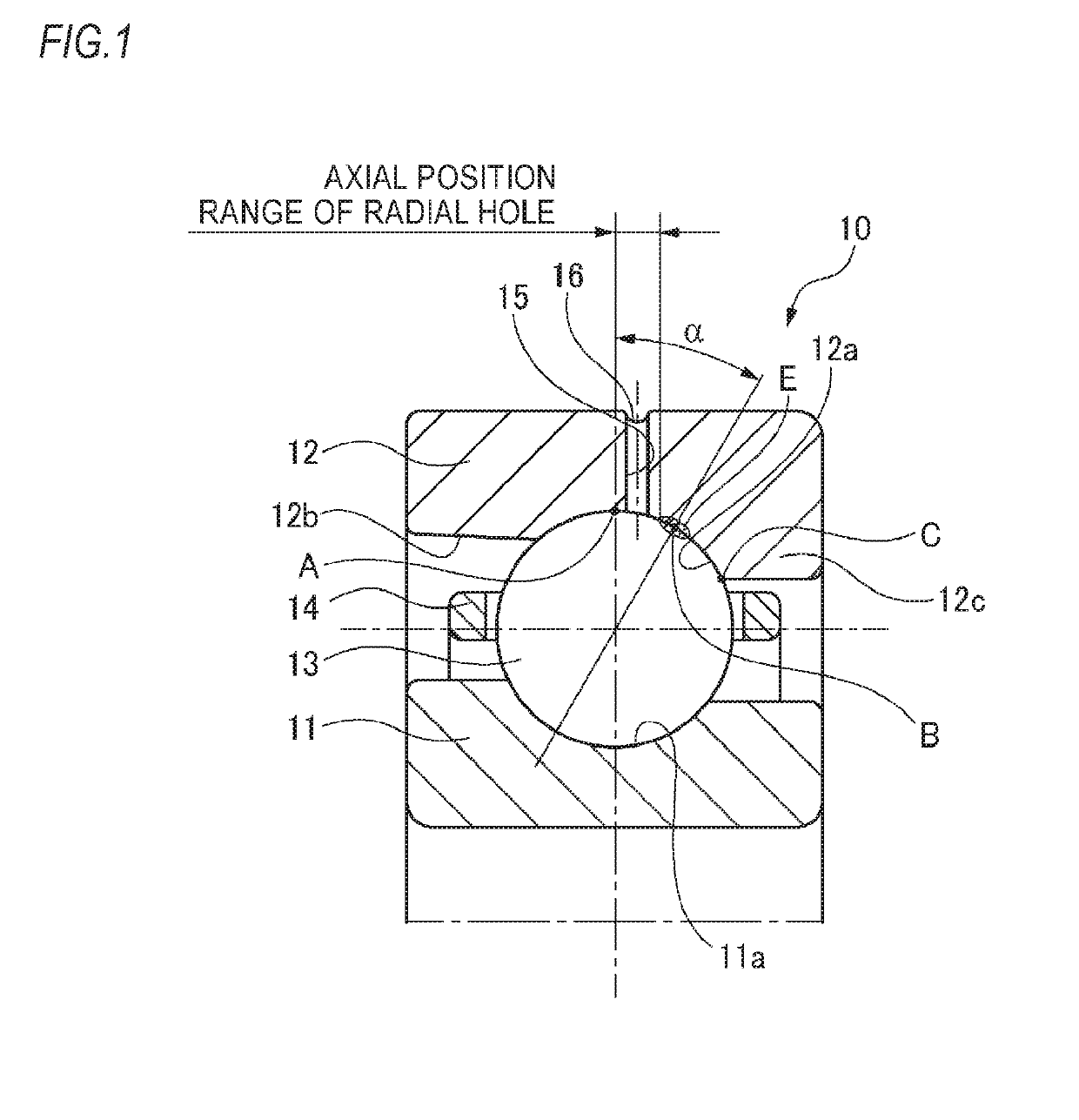
[0072]A thrust angular ball bearing 10 in accordance with a first embodiment is incorporated to a lathe spindle and is generally used in a low-speed (dmn value: 600,000 or lower) region. Also, since a high external axial load generated during processing is applied, the thrust angular ball bearing 10 is used in a state where a high initial preload of about 1000 to 6000N is applied.
[0073]As shown in FIG. 1, the thrust angular ball bearing 10 includes an inner ring 11 having a circular arc-shaped inner ring raceway groove 11a formed in an outer peripheral surface, an outer ring 12 having a circular arc-shaped outer ring raceway groove 12a formed in an inner peripheral surface, and a plurality of balls 13 each of which is held by a cage 14, has a predetermined contact angle α and is arranged rollably between the inner ring raceway groove 11a and the outer ring raceway groove 12a. One axial inner peripheral surface of the outer ring 12 is formed with a counterbore 12b, and the other axia...
second embodiment
[0092]Subsequently, a ball bearing of a second embodiment is described with reference to FIG. 5.
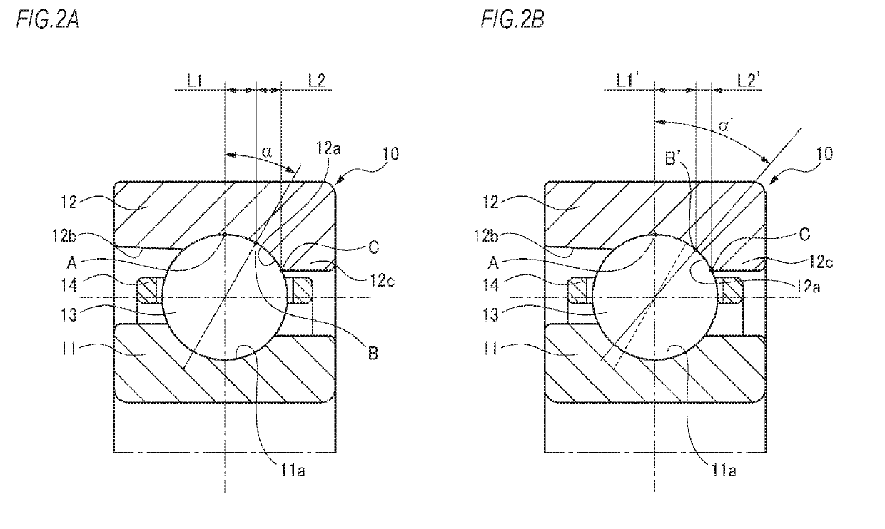
[0093]A ball bearing 10a of the second embodiment is incorporated to a spindle that is to be used in a high-speed region, like a spindle for machining center, the contact angle α is set smaller than the first embodiment, and the axial position of the inner diameter-side opening of the radial hole 15 is also different from the first embodiment. That is, in the second embodiment, as shown in FIG. 5, the axial position of the inner diameter-side opening of the radial hole 15 is located in the outer ring raceway groove 12a at an opposite side to the groove bottom A of the outer ring 12 with respect to the contact point (contact position B) of the ball 13 and the outer ring 12 and is spaced from the contact ellipse E between the ball 13 and the outer ring raceway groove 12a.
[0094]For the ball bearing 10a that is to be used at high speed, a constant pressure preload type (a type of applying a ...
PUM
| Property | Measurement | Unit |
|---|---|---|
| contact angle | aaaaa | aaaaa |
| radius measuring method | aaaaa | aaaaa |
| contact angle | aaaaa | aaaaa |
Abstract
Description
Claims
Application Information