AI technical title is built by Patsnap AI team. It summarizes the technical point description of the patent document.
a control system and locomotive technology, applied in the field of communication data, can solve the problems of significant delays and financial losses, vehicle non-operation, damage and/or failure of various subsystems, etc., to reduce the occurrence of damage and/or failure, and increase the extent of delays and financial losses.
Inactive Publication Date: 2019-06-13
TRANSPORTATION IP HLDG LLC
View PDF0 Cites 55 Cited by
Summary
Abstract
Description
Claims
Application Information
AI Technical Summary
This helps you quickly interpret patents by identifying the three key elements:
Problems solved by technology
Method used
Benefits of technology
Benefits of technology
This patent is about a system that uses sensors and data to detect issues and hazards in a transportation network and alert operators or control components to prevent accidents. The system can identify hazards like damaged routes, switches, or vehicles and determine the best way to respond to them. This can include slowing down, stopping, or changing the vehicle's direction of movement. The system can also adjust the trip plan based on information about the route and the locomotive's engine system to optimize fuel efficiency and reduce emissions output. Overall, this patent describes a system that uses sensors and data to make transportation safer and more efficient.
Problems solved by technology
Over time, the various subsystems may become damaged and / or fail.
Unexpected damage and / or failure of some subsystems may cause the vehicle to be non-operational for a downtime period until the subsystem is repaired.
Such downtime periods can result in significant delays and financial losses.
Furthermore, the failures of some subsystems, such as a propulsion subsystem or a cooling subsystem, can leave a vehicle debilitated on a route.
The debilitated vehicle can block movement of other vehicles along the route, increasing the extent of the delays and financial losses attributable to the failed subsystem.
One way to reduce the occurrence of damage and / or failure to the subsystems of a vehicle is to increase the frequency at which the subsystems are inspected, repaired, and / or replaced, but such actions can be time consuming and expensive.
The time spent to inspect the vehicles reduces the time that the vehicles are in operation, therefore reducing the productivity and financial gain of the vehicles.
Furthermore, even routine inspections may not reduce damage and / or failure of the subsystems.
For example, the root cause of damage to a subsystem may occur after one inspection and cause the subsystem to fail before a subsequent inspection.
Additionally, it may be difficult to identify and diagnose a root cause of damage to a subsystem during an inspection.
The vehicle system may not be used efficiently if the path over which it travels is in disrepair.
For example, a train (including both a locomotive and a series of rail cars) may derail if the rails are not within designated specifications.
Railroads may experience many derailments per year.
In addition to the repair work to the rails, the resulting costs include network congestion, idled assets, lost merchandise, and the like.
Contributing aspects to derailments may include damaged or broken rails and wheels.
Method used
Image
Click on the blue label to locate the original text in one second.
Reading with bidirectional positioning of images and text.
Examples
Embodiment Construction
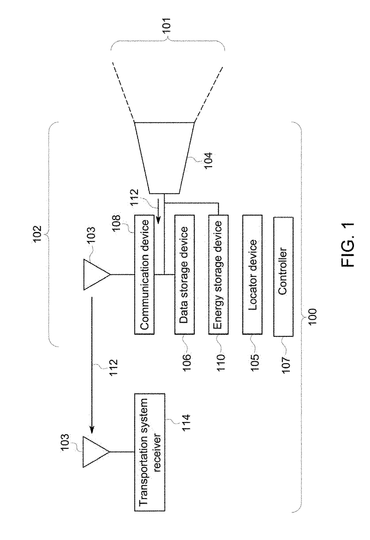
[0104]Embodiments described herein relate to sensor packages for capturing and communicating data, particularly with regard to a transportation system or network. For example, a sensor package (e.g., a video / IR camera, microphone, accelerometer, radiationdetector, LIDAR) may be connected or otherwise disposed onboard a mobile platform (e.g., a driverless or remotely controlled automobile, drone, marine vessel, helicopter, or airplane) to allow the sensor package unit to move. The transportation system or network can include interconnected routes (e.g., tracks, roads, waterways, or other paths), wayside devices, and / or other components, such as bridges, tunnels, gates, etc.
[0105]An aerial unmanned vehicle (also referred to as a drone) may be used as an example of the mobile platform, which, in this example, may have a video camera supported on the drone. The drone can move along a route ahead of a non-aerial transport vehicle and can communicate image data back to the non-aerial veh...
PUM
Abstract
System includes a controller configured to obtain one or more of a route parameter or a vehicle parameter from discrete examinations of one or more of a route or a vehicle system. The route parameter is indicative of a health of the route over which the vehicle system travels. The vehicle parameter is indicative of a health of the vehicle system. The discrete examinations of the one or more of the route or the vehicle system separated from each other by one or more of location or time. The controller is configured to examine the one or more of the route parameter or the vehicle parameter to determine whether the one or more of the route or the vehicle system is damaged. The system also includes examination equipment configured to continually monitor the one or more of the route or the vehicle system responsive to determining that the one or more of the route or the vehicle is damaged.
Description
CROSS-REFERENCE TO RELATED APPLICATIONS[0001]The present application is a continuation-in-part of U.S. patent application Ser. No. 16 / 195,950 (“the '950 Application”), filed on 20 Nov. 2018, which is a continuation of U.S. patent application Ser. No. 15 / 651,630 (“the '630 Application”) filed on 17 Jul. 2017, which claims priority to U.S. Provisional Application No. 62 / 403,963, filed 4 Oct. 2016. The '630 Application is a continuation-in-part of U.S. patent application Ser. No. 14 / 624,069 (“the '069 Application”), filed 17 Feb. 2015, and is a continuation-in-part of U.S. patent application Ser. No. 15 / 044,592 (“the '592 Application”), filed 16 Feb. 2016.[0002]The '950 Application is also a continuation-in-part of U.S. patent application Ser. No. 11 / 750,716 filed 18 May 2007, which claims priority to U.S. Provisional Application No. 60 / 894,006, filed 9 Mar. 2007, and is also a continuation-in part of U.S. application Ser. No. 11 / 385,354, filed 20 Mar. 2006.[0003]The '069 Application c...
Claims
Application Information
Patent Timeline
Application Date:The date an application was filed.
Publication Date:The date a patent or application was officially published.
First Publication Date:The earliest publication date of a patent with the same application number.
Issue Date:Publication date of the patent grant document.
PCT Entry Date:The Entry date of PCT National Phase.
Estimated Expiry Date:The statutory expiry date of a patent right according to the Patent Law, and it is the longest term of protection that the patent right can achieve without the termination of the patent right due to other reasons(Term extension factor has been taken into account ).
Invalid Date:Actual expiry date is based on effective date or publication date of legal transaction data of invalid patent.

