Treatment method of an aqueous solution containing urea, ammonia and carbon dioxide and treatment equipment therefor

a technology of aqueous solution and ammonia, which is applied in the direction of water treatment multi-stage treatment, separation process, and water treatment water, etc. it can solve the problems of insufficient removal of small amount of unreacted ammonia and carbon dioxide, and inability to adequately remove ammonia in the presence of urea in water. , to achieve the effect of saving heating steam supply to the urea hydrolyzer, the reduction

Active Publication Date: 2019-06-13
TOYO ENG CORP
View PDF0 Cites 6 Cited by
  • Summary
  • Abstract
  • Description
  • Claims
  • Application Information

AI Technical Summary

Benefits of technology

[0038]According to the present invention, since the amount of an aqueous solution to be introduced into the urea hydrolyzer is reduced, the load on the urea hydrolyzer and the second stripper is lowered. As a result, the amount of heating steam supplied to the urea hydrolyzer can be saved. At the same time, both equipments can be made compact. Note that the amount of steam that can be saved here mainly means the amount of heating steam supplied directly to the urea hydrolyzer or strippers, but in the case of applying heat using a heat exchanger instead of direct supply of heating steam, it also means the amount of heating steam supplied to the heat exchanger.
[0039]Further, even if an aqueous solution utilized as makeup water for an exhaust gas treatment equipment (for example, drainage resulting from the concentration step of a urea synthesis solution) contains ammonia, emission of ammonia into atmospheric air is suppressed since the exhaust gas treatment equipment has an equipment to suppress emission of ammonia.

Problems solved by technology

However, a small amount of unreacted ammonia and carbon dioxide are also contained in the drainage (evaporated water) of this concentration step.
However, ammonia is contained in the water obtained by concentrating the urea synthesis solution, and if this water is supplied to the urea dust scrubbing equipment as it is, the amount of ammonia emitted into atmospheric air will undesirably increase.
The reason why the urea hydrolyzer is used here is that it is difficult to sufficiently remove ammonia in the presence of urea in water.

Method used


Image

  • Treatment method of an aqueous solution containing urea, ammonia and carbon dioxide and treatment equipment therefor
  • Treatment method of an aqueous solution containing urea, ammonia and carbon dioxide and treatment equipment therefor
  • Treatment method of an aqueous solution containing urea, ammonia and carbon dioxide and treatment equipment therefor

Examples


example 1 (fig.1)

Example 1 (FIG. 1)

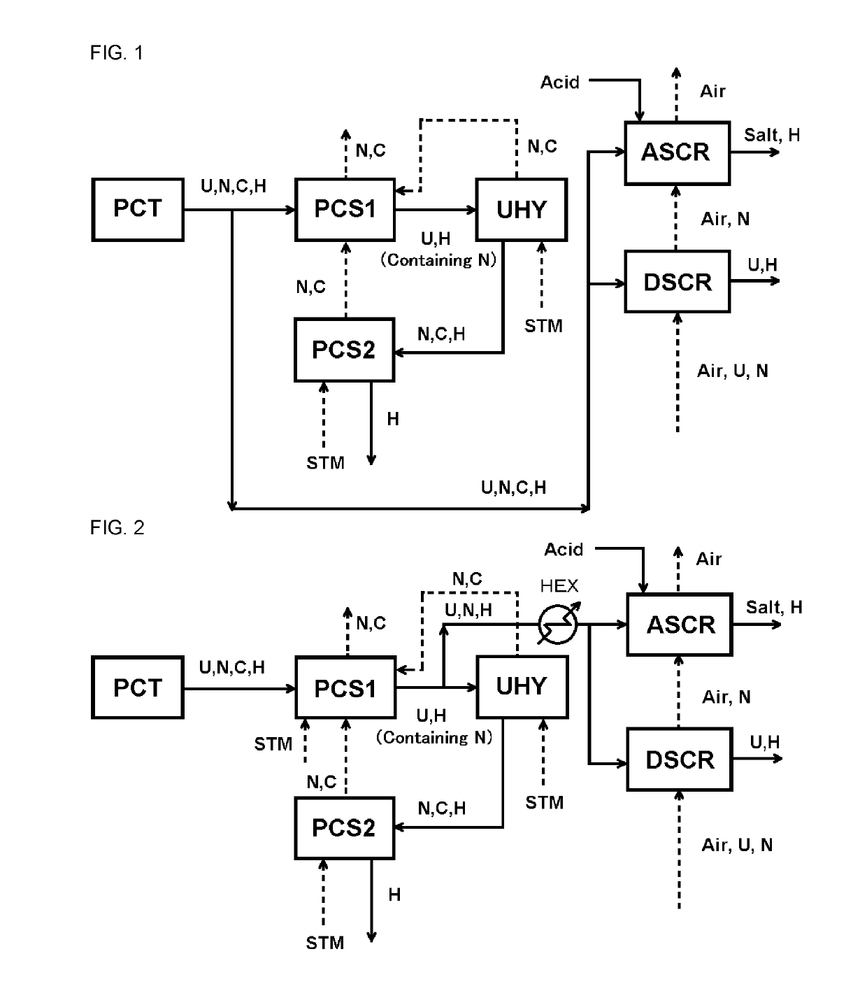
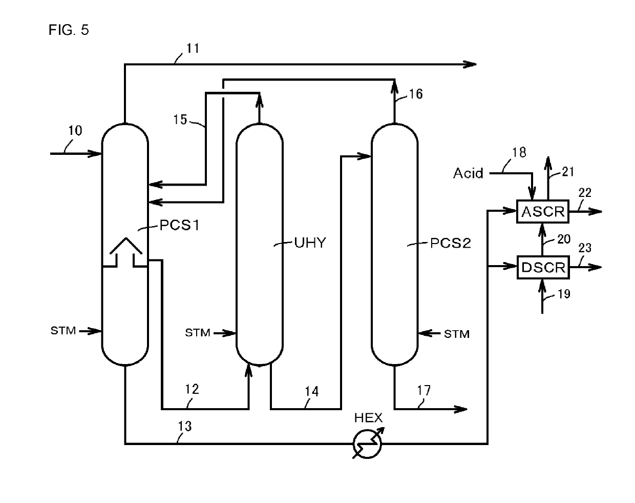
[0073]From 35512 kg / hr of an aqueous solution discharged from a urea production equipment with a daily output of 2100 tons, which is an aqueous solution of 48° C. containing 414 kg / hr (1.17% by mass) of urea, 784 kg / hr (2.21% by mass) of ammonia and 491 kg / hr (1.38% by mass) of carbon dioxide, 25090 kg / hr of the aqueous solution is fed to a urea dust scrubbing equipment (DSCR) and an ammonia scrubbing equipment (ASCR) as makeup water and 10422 kg / hr of the aqueous solution is fed to a first stripper (PCS1).

[0074]The aqueous solution that is sent to the first stripper (PCS1) is pressurized by a pump, raised to 85° C. with a heat exchanger, and introduced to the top of the first stripper (PCS1) operating at 3 bar G. The top gas of the second stripper (PCS2) is introduced to the bottom of the first stripper (PCS1), and the top gas of the urea hydrolyzer (UHY) is supplied as the steam for stripping to the middle stage of the first stripper (PCS1). Ammonia and carbon di...

example 2 (fig.2)

Example 2 (FIG. 2)

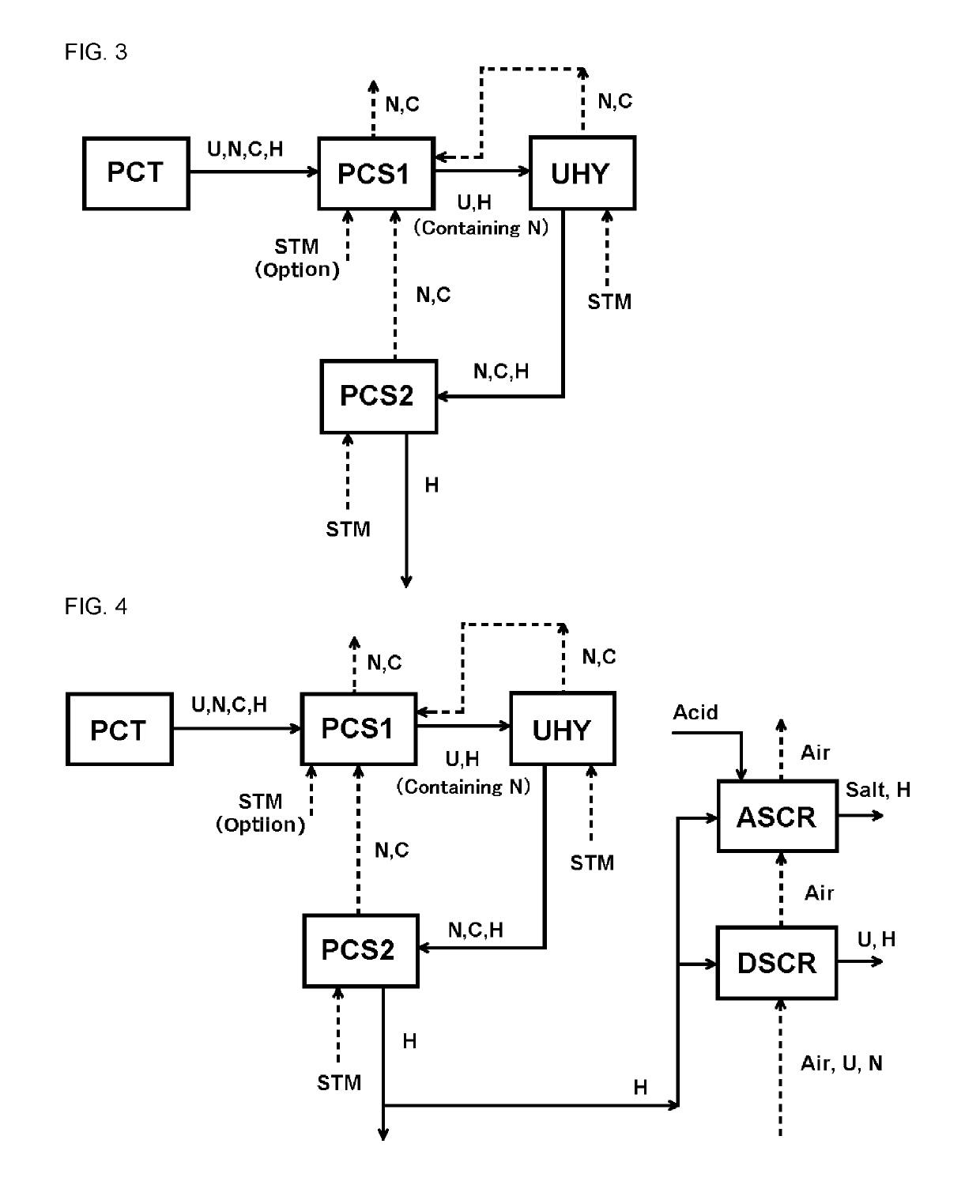
[0082]35512 kg / hr of an aqueous solution discharged from a urea production equipment with a daily output of 2100 tons, which is an aqueous solution of 48° C. containing 414 kg / hr (1.17% by mass) of urea, 784 kg / hr (2.21% by mass) of ammonia and 491 kg / hr (1.38% by mass) of carbon dioxide is pressurized by a pump, heated to 85° C. by a heat exchanger and introduced to the top of the first stripper (PCS1) operated at 3 bar G.

[0083]The top gas of the second stripper (PCS2) is introduced to the middle stage of the first stripper (PCS1), and the top gas of the urea hydrolyzer (UHY) is supplied as the steam for stripping to the middle stage. In addition, 2180 kg / hr of the steam for stripping is supplied to the bottom. Ammonia and carbon dioxide in the aqueous solution are separated and the gas is discharged from the top of the column at 132° C. The composition of the discharged gas is shown as 809 kg / hr of ammonia, 623 kg / hr of carbon dioxide and 2752 kg / hr of steam. Thi...


PUM

PropertyMeasurementUnit
temperatureaaaaaaaaaa

Abstract

Disclosed are: a treatment method comprising (1) a step in which an aqueous solution containing urea, ammonia and carbon dioxide is introduced into a first stripper (PCS1) and subjected to stripping, and the aqueous solution after stripping is introduced into a urea hydrolyzer (UHY), (2) a step in which urea in the aqueous solution is hydrolyzed in the urea hydrolyzer (UHY), and the aqueous solution after hydrolysis is introduced into a second stripper (PCS2), (3) a step in which the aqueous solution is subjected to stripping in the second stripper (PCS2), and (4) a step in which a part of the aqueous solution before being stripped in the first stripper (PCS1), and / or, a part of the aqueous solution after being stripped in the first stripper (PCS1) but before being hydrolyzed in the urea hydrolyzer (UHY) is introduced into an exhaust gas treatment equipment equipped with an ammonia scrubbing equipment (ASCR); and a treatment equipment therefor.

Description

TECHNICAL FIELD[0001]The present invention relates to a treatment method in which urea in an aqueous solution containing urea, ammonia and carbon dioxide is hydrolyzed and ammonia and carbon dioxide in the aqueous solution are separated and recovered; and a treatment equipment therefor. More specifically, the present invention relates to a treatment method in which it is possible to reduce the amount of heating steam and make the equipment compact by lowering the load of a urea hydrolyzer without lowering the hydrolysis efficiency of urea, and furthermore, emission of ammonia into atmospheric air is suppressed even if a part of the aqueous solution is introduced into an exhaust gas treatment equipment of a urea production equipment; and a treatment equipment therefor.BACKGROUND ART[0002]A urea synthesis solution obtained by reacting ammonia and carbon dioxide under high temperature and high pressure contains urea generated, water, unreacted ammonia and carbon dioxide. The urea synth...

Claims


Application Information

Patent Timeline
Patent Type & Authority Applications(United States)
IPC IPC(8): C02F1/02C02F1/20B01D3/00B01D19/00B01D53/78
CPCC02F1/025C02F1/20B01D3/009B01D19/001B01D53/78C02F2101/16C02F2103/36C02F2209/02C02F2209/03C02F2301/08B01D3/143B01D3/38C07C273/02C02F2101/38C02F1/66Y02P20/10Y02P20/151Y02P70/10B01D3/00B01D53/58C07C273/00C01C1/28
Inventor SASAKI, KEIGO
Owner TOYO ENG CORP
Why Eureka
Try Eureka