Stationary Magic Angle Spinning Enhanced Solid State Spin Sensor

a technology of spin sensor and magic angle, which is applied in the direction of magnetic measurement, instruments, measurement devices, etc., can solve the problems of greater electrical power loss in the first pair of coils and the second pair of coils than in the electrical power loss, and achieve the effect of increasing the dephasing tim

Active Publication Date: 2019-06-13
MASSACHUSETTS INST OF TECH
View PDF0 Cites 6 Cited by
  • Summary
  • Abstract
  • Description
  • Claims
  • Application Information

AI Technical Summary

Benefits of technology

[0021]Other embodiments include a method of measuring an external magnetic field experienced by color center defects in a solid-state host. This method includes applying a permanent magnetic field to the color center defects along a first axis and applying a rotating magnetic field to the color center defects. Th

Problems solved by technology

And electrical power loss in the first pair of coils and the second pair of coils can be

Method used


Image

  • Stationary Magic Angle Spinning Enhanced Solid State Spin Sensor
  • Stationary Magic Angle Spinning Enhanced Solid State Spin Sensor
  • Stationary Magic Angle Spinning Enhanced Solid State Spin Sensor

Examples


Embodiment Construction

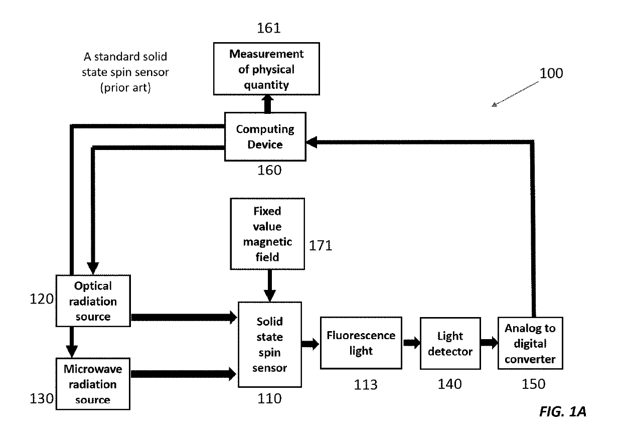
[0045]In sensing an external magnetic field with a solid-state sensor, the sensitivity and signal-to-noise ratio (SNR) of the measurement depends in part on the sensor's dephasing or dephasing time, T2*. The T2* dephasing time characterizes the time over which the color center defects within the solid-state spin sensor undergo inhomogeneous dephasing. The T2* dephasing time is also sometimes called the free induction decay time. Since inhomogeneous dephasing of the color center defects within the solid-state spin sensor results in loss of information, the T2* dephasing time sets an approximate limit on the sensing time for a single measurement.

[0046]In practice, the length of a single measurement is limited to an interrogation time less than or about equal to the T2* dephasing time. Since longer interrogation times yield more sensitive measurements and higher signal-to-noise ratios, it is usually highly desirable for a solid-state spin sensor to have the longest possible T2* dephasi...


PUM


Abstract

Here we present a solid-state spin sensor with enhanced sensitivity. The enhanced sensitivity is achieved by increasing the T2* dephasing time of the color center defects within the solid-state spin sensor. The T2* dephasing time extension is achieved by mitigating dipolar coupling between paramagnetic defects within the solid-state spin sensor. The mitigation of the dipolar coupling is achieved by applying a magic-angle-spinning magnetic field to the color center defects. This field is generated by driving a magnetic field generator (e.g., Helmholtz coils) with phase-shifted sinusoidal waveforms from current source impedance-matched to the magnetic field generator. The waveforms may oscillate (and the field may rotate) at a frequency based on the precession period of the color center defects to reduce color center defect dephasing and further enhance measurement sensitivity.

Description

CROSS-REFERENCE TO RELATED APPLICATION(S)[0001]This application claims the priority benefit, under 35 U.S.C. § 119(e), of U.S. Application No. 62 / 591,859, entitled “Stationary Magic Angle Spinning Enhanced Solid-state spin sensor,” which was filed on Nov. 29, 2017, and is incorporated herein by reference in its entirety.GOVERNMENT SUPPORT[0002]This invention was made with Government support under Contract No. FA8721-05-D-0001 awarded by the U.S. Air Force. The Government has certain rights in the invention.BACKGROUND[0003]Sensors based on solid-state spin systems offer high-performance, low-cost, low-power platforms for sensing or imaging of magnetic fields, electric fields, temperature, pressure, and other physical quantities, sometimes with resolution down to the nanoscale. A solid-state spin sensor employs color center defects (e.g., nitrogen vacancies), which are point-like defects in a solid-state host (e.g., diamond or silicon carbide), to measure physical quantities. The colo...

Claims


Application Information

Patent Timeline
IPC IPC(8): G01R33/26
CPCG01R33/26G01N24/12G01R33/307G01R33/34061G01R33/3607G01R33/3678G01R33/445
Inventor BARRY, JOHN F.BRAJE, DANIELLE A.EISENACH, ERIK R.MCNALLY, CHRISTOPHER MICHAELO'KEEFFE, MICHAEL F.PHAM, LINH M.
Owner MASSACHUSETTS INST OF TECH
Why Eureka
Try Eureka