
Resistive element and method of manufacturing the resistive element

Active Publication Date: 2019-06-13
FUJI ELECTRIC CO LTD
View PDF2 Cites 3 Cited by
  • Summary
  • Abstract
  • Description
  • Claims
  • Application Information

AI Technical Summary

Benefits of technology

The present invention provides a resistive element that is smaller and has fewer bonding wires compared to previous techniques. This patent also provides a method for manufacturing the resistive element. This invention solves problems associated with large resistive elements and few bonding wires.

Problems solved by technology

This structure leads to an increase in size of a chip and requires two bonding wires connected to the two electrodes.

Method used


Image

  • Resistive element and method of manufacturing the resistive element
  • Resistive element and method of manufacturing the resistive element
  • Resistive element and method of manufacturing the resistive element

Examples


first modified example

[0073]A resistive element according to a first modified example of the embodiment of the present invention illustrated in FIG. 20 differs from the resistive element illustrated in FIG. 1 in further including auxiliary films 3c and 3d in a floating state in terms of potential allocated on the first insulating films 2a and 2b and separated from the resistive layers 3a and 3b.

[0074]The auxiliary film 3c is deposited below the first electrode 5a of the paired first electrodes 5a and 5b and separated from the resistive layer 3a. The auxiliary film 3d is deposited below the other first electrode 5b and separated from the resistive layer 3b. The auxiliary films 3c and 3d are made of the same material as the resistive layers 3a and 3b, such as n-type doped polysilicon, and have the same thickness as the resistive layers 3a and 3b. The auxiliary films 3c and 3d have a rectangular planar pattern, for example. The other structures in the resistive element according to the first modified examp...

second modified example

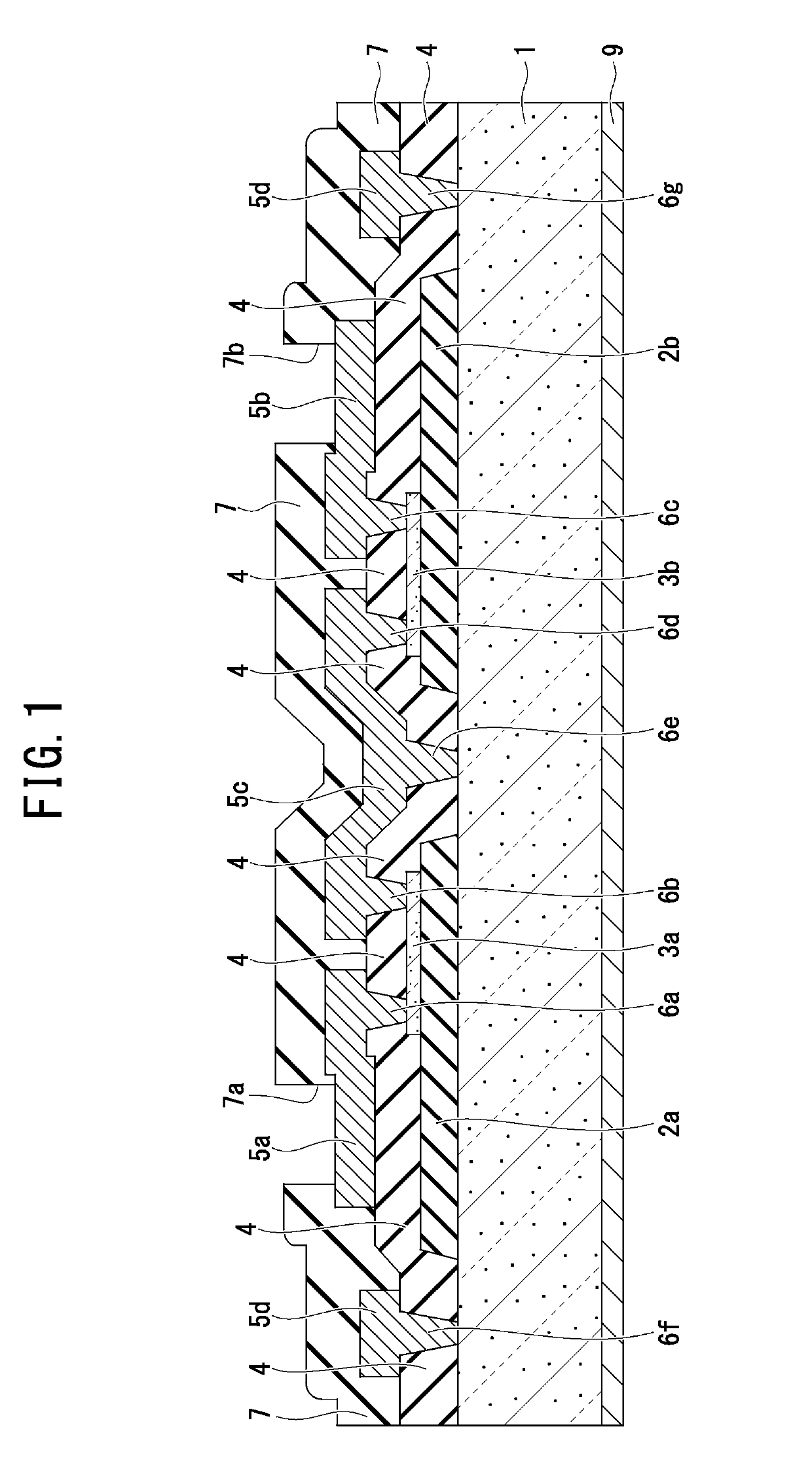
[0077]The resistive element according to the embodiment of the present invention described above includes the plural first insulating films 2a and 2b, resistive layers 3a and 3b, and first electrodes 5a and 5b, and the single relay wire 5c electrically connected to each one end of the resistive layers 3a and 3b, as illustrated in FIG. 1. A resistive element according to a second modified example of the embodiment of the present invention illustrated in FIG. 21 differs from the resistive element illustrated FIG. 1 in including a plurality of resistive layers 3a and 3b and relay wires 5f and 5g, and a single first electrode 5e electrically connected to each one end of the resistive layers 3a and 3b.

[0078]An auxiliary film 3e in a floating state in terms of potential is deposited on a first insulating film 2c and separated from the resistive layers 3a and 3b so as to be interposed between the resistive layers 3a and 3b. The auxiliary layer 3e is made of the same material as the resist...


PUM


Abstract

A resistive element includes: a semiconductor substrate; a first insulating film deposited on the semiconductor substrate; a resistive layer deposited on the first insulating film; a second insulating film deposited to cover the first insulating film and the resistive layer; a first electrode deposited on the second insulating film and electrically connected to the resistive layer; a relay wire deposited on the second insulating film without being in contact with the first electrode, and including a resistive-layer connection terminal electrically connected to the resistive layer and a substrate connection terminal connected to the semiconductor substrate with an ohmic contact; and a second electrode deposited on a bottom side of the semiconductor substrate, wherein a resistor is provided between the first electrode and the second electrode.

Description

CROSS-REFERENCE TO RELATED APPLICATION[0001]This application claims benefit of priority under 35 USC 119 based on Japanese Patent Application No. 2017-238887 filed on Dec. 13, 2017, the entire contents of which are incorporated by reference herein.BACKGROUND OF THE INVENTION1. Field of the Invention[0002]The present invention relates to a resistive element and a method of manufacturing the resistive element.2. Description of the Related Art[0003]JPH08-306861 discloses a resistive element for a semiconductor device, such as a semiconductor integrated circuit (IC), in which an insulating layer is deposited on a silicon substrate, and a thin-film resistive layer is deposited on the insulating layer. The resistive element disclosed in JPH08-306861 includes two electrodes connected to the resistive layer on both sides opposed to each other to which aluminum thin wires are bonded.[0004]The resistive element disclosed in JPH08-306861 has a structure with the two electrodes opposed to each ...

Claims


Application Information

Patent Timeline
IPC IPC(8): H01L23/522H01L49/02H01L23/00
CPCH01L23/5228H01L28/26H01L28/24H01L24/49H01L2924/13055H01L2224/04042H01L2224/05166H01L2224/05624H01L2224/02166H01L2224/32245H01L2224/83801H01L2224/29101H01L2224/05644H01L2224/05155H01L2224/05082H01L2224/04026H01L24/29H01L24/83H01L24/05H01L24/32H01L24/03H01L2224/023H01L2924/01007H01L2924/01014H01L2924/01029H01L2924/013H01L2924/00014H01L2924/014H01L2924/0001
Inventor KARINO, TAICHISUMIDA, HITOSHISAITO, MASARUYAMAJI, MASAHARUSASAKI, OSAMU
Owner FUJI ELECTRIC CO LTD
Learn More