Display apparatus and computing apparatus including the same
a technology of computing apparatus and display device, which is applied in the direction of transducer diaphragm, details of portable computers, instruments, etc., can solve the problems of difficult to realize high sound quality, low band base sound is not sufficient, and sound quality may be degraded, so as to improve the sound characteristic of low-pitched sound band
- Summary
- Abstract
- Description
- Claims
- Application Information
AI Technical Summary
Benefits of technology
Problems solved by technology
Method used
Image
Examples
first embodiment
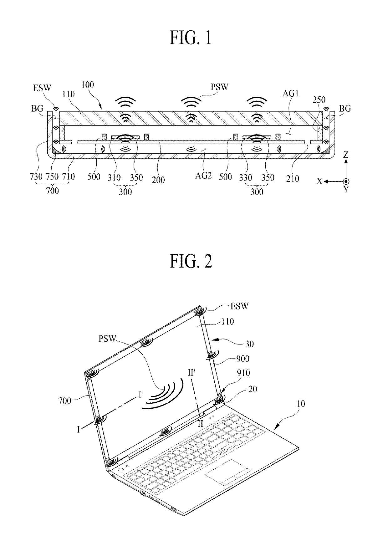
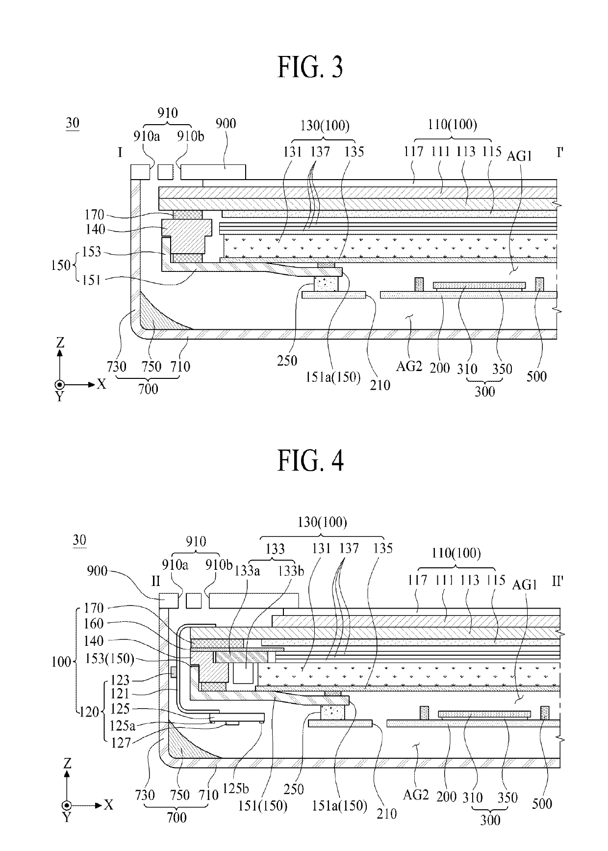
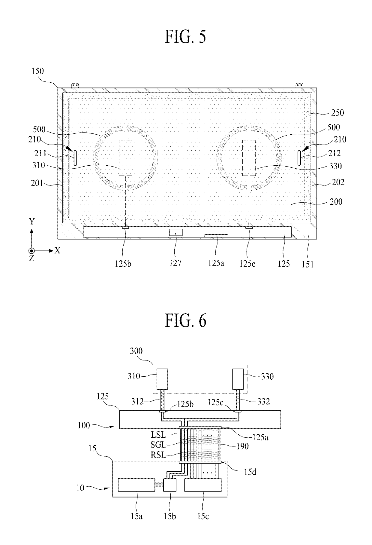
[0097]The vibration plate 200 according to an embodiment of the present disclosure may include a communication part 210 between the plate securing member 250 and the vibration module 300. The communication part 210 according to the present disclosure may include a plurality of first communication holes 211 and 212, which may be between each of the first and second vibration elements 310 and 330 and the plate securing member 250 with respect to a first lengthwise direction X of the display module 100.
[0098]One first communication hole 211 of the plurality of first communication holes 211 and 212 may be in a first periphery of the vibration plate 200 adjacent to a first sidewall 201 of the vibration plate 200, and the other first communication hole 212 of the plurality of first communication holes 211 and 212 may be in a second periphery of the vibration plate 200 adjacent to a second sidewall 202 of the vibration plate 200. For example, the communication part 210 according to a first...
second embodiment
[0154]In the communication part 210 according to the present disclosure, by further extending an air gap, which may be a space enabling the display module 100 and the vibration plate 200 to vibrate through the middle communication hole 213 between the first and second vibration elements 310 and 330, air may more smoothly flow between first and second air gaps when the vibration plate 200 vibrates (or shakes). Therefore, the vibration plate 200 may vibrates stably. Thus, a sound pressure characteristic and a frequency characteristic of a low-pitched sound band, based on the vibration of the vibration plate 200, may be enhanced.
[0155]With reference to the example of FIG. 11, along with the FIG. 5 example, a communication part 210 according to the third embodiment of the present disclosure may include a plurality of first communication holes 211 and 212, a middle communication hole 213, and a plurality of second communication holes 214 and 215. The communication part 210 according to t...
third embodiment
[0158]Moreover, the one communication hole 211 of the plurality of first communication holes 211 and 212 may be on the left with respect to the first vibration element 310, and the plurality of second communication holes 214 and 215 may be over and under the first vibration element 310. Also, the other communication hole 212 of the plurality of first communication holes 211 and 212 may be on the right with respect to the second vibration element 330, and the plurality of second communication holes 214 and 215 may be over and under the second vibration element 330. In the communication part 210 according to the present disclosure, the middle communication hole 213 may be omitted.
[0159]In the communication part 210 according to the third embodiment of the present disclosure, by further extending an air gap, which may be a space enabling the display module 100 and the vibration plate 200 to vibrate through the plurality of first communication holes 211 and 212, the middle communication...
PUM
 Abstract
Description
Claims
Application Information
 - R&D
- Intellectual Property
- Life Sciences
- Materials
- Tech Scout
- Unparalleled Data Quality
- Higher Quality Content
- 60% Fewer Hallucinations
Browse by: Latest US Patents, China's latest patents, Technical Efficacy Thesaurus, Application Domain, Technology Topic, Popular Technical Reports.
© 2025 PatSnap. All rights reserved.Legal|Privacy policy|Modern Slavery Act Transparency Statement|Sitemap|About US| Contact US: help@patsnap.com


